UV Editor new look and feel

UV Editor improvements
- Menu organization: The menus along the top of the editor have been re-organized for a more streamlined workflow. For more information, see UV Editor menu bar.
- Drag Select: It is now possible to drag select components either by activating Drag via Tool Settings or by holding Tab and dragging across them with the left mouse button.
- Grow Selection and Shrink Selection: You can now expand and contract the current selection in the UV Editor by Ctrl + right-clicking the current selection and selecting either option. See Select UVs.
- Texture selection: It is now easier to switch between textures applied to the selected geometry via the UV Editor's Texture menu. You can also instantly apply checker patterns for easier UV adjustments from here. For more information, see UV Editor Textures menu.
- Selection performance: Selecting and deselecting a high number of UVs on a dense mesh in the UV Editor is now significantly faster.
- UV sets for multiple objects: The UV Editor is now capable of displaying UV sets associated with all currently selected objects, organized into a table within the UV Set Editor.
- UV selection consistency: The UV Editor will now automatically convert your current selection to the appropriate one before applying certain commands. This saves you from having to perform these conversions manually. After performing these commands, the current selection will then return you to your original UV selection. These commands include:
- Normalize
- Unitize
- Flip
- Rotate
- Grid
- Align
- Straighten UV Border
- Sew UV Edges
- Merge UVs
- Separate the selected UV into one for each connected edge
- Split UVs on multiple meshes: The Split UVs operation now works when multiple objects are selected at the same time.
- Improved visibility: When Display Image is enabled with Color Correction, but no texture is loaded, the background no longer changes color.
- Wireframe appearance: You can now modify the color and alpha values of UV shells in the UV Editor. For more information, see UV Editor View menu.
- Multicolor UV Shell display: You now have the option to shade UV shells different colors both in the UV Editor and the Viewport to better differentiate them. For more information, see the UV Editor View menu.
- UV Distortion transparency: You can now modify the alpha values of UV distortion display. For more information, see the UV Editor View menu.
- Finer dimming control: You can now control how much a texture is dimmed in the UV Editor with the Dim options.
- Selection Constraint: You can now narrow your component selection to something more specific, or select edge rings between texture borders using the Select Tool settings.
- Convert to Edge Ring / Contained Faces / Face Path now work in the UV Editor. For more information, see the Select menu.
- Prevent Negative Scale now works in the UV Editor. For more information, see the Scale Tool.
- Grid color and default values: You can now adjust the colors of the UV Grid. Additionally, UV Grid default values have been changed to better reflect modern UV workflows. For more information, see UV Editor View menu.
- Isolate Select HUD: The heads-up display now shows when you are in Isolate Select mode. You can toggle this on and off from the UV Editor View menu.
- Flip UVs cut UV edges: You can now control whether or not the Flip UVs command automatically cuts UV edges when flipping components on a UV Shell. For more information, see Flip UVs options.
- Map Borders on multiple objects: You can now map UV borders on multiple shells at once, either by selecting multiple shells or groups of UVs on multiple shells.
- Alt + X and Alt + Y can now be used to undo or redo view changes (just like the Viewport).
UV Shell marking menu
You can access a new UV Shell marking menu in the viewport by Shift + right-clicking when in UV shell selection mode. This is useful for quickly editing UV shells without having to go to the UV Editor. For more information, see Marking Menus.
Circularize command
Object / Component selection mode consistent across 3D view and UV Editor
The UV Editor is now aware of the 3D view's current selection mode and vice versa. This means that you can select a few components in the 3D view, switch to the UV Editor, and continue selecting those same types of components without having to manually switch modes again first.
Cut and Sew UV edges in the Viewport
Harden edges along texture border
You can now easily harden all polygon edges that lie along a texture border and vice versa via the Soften / Harden Edge command or by using Auto Seams.
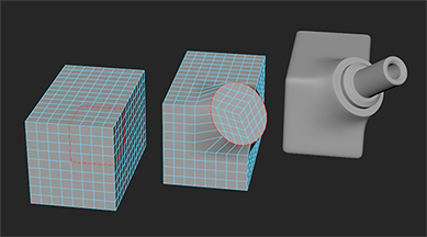
New primitive objects
Local component transformation
- Ctrl + middle-drag with the Move Tool to translate components along their individual normals.
- Ctrl + middle-drag with the Rotate Tool to rotate components around their individual X axes.
- Ctrl + middle-drag with the Scale Tool to scale components along their individual YZ axes.
Bevel improvements
A post-process has been added to Bevel that makes the results more consistent, particularly when Chamfering is off.
Quick Edge Constraint hotkey
You can now Ctrl + Shift drag any manipulator handle to quickly transform with the Transform Constraint set to Edge mode. For more information, see Slide polygon components.
Smart Extrusion hotkey
Smart Duplicate hotkey
Symmetrize Command
In addition to the Symmetrize Tool, there is now a Symmetrize command that you can use to symmetrize selected UVs. For more information, see Symmetrize UVs.
Global symmetry
Symmetry is now respected across all tools. You can change symmetry via the Symmetry drop-down in the Status Line. For more information, see the Status Line.
Topological symmetry support for sculpting
Previous live surfaces selection
A drop down menu has been added to the Live Surface field that gives access to a history of other surfaces previously made live. For more information, see Set a live surface .
Multi-Cut enhancements on live surfaces
Multi-Cut Ignore Backfaces
You can now set the Multi-Cut Tool to cut only faces visible to the camera during a slice operation. This is helpful for avoiding accidental cuts. For more information, see Slice faces with the Multi-Cut Tool and Multi-Cut Tool options.
Multi-Cut Slice snapping support
You can now use grid (hold X) and point (hold V) snapping to place more precise slice points. For more information, see Slice faces with the Multi-cut Tool..
Quad Draw enhancements
- Surface visibility: Quad Draw overlays are now more visible on live surfaces. You can also manually control the color and transparency. For more information, see Quad Draw Tool Options.
- Quad Draw on selected: Activating the Quad Draw Tool while an object is selected now uses that object for Quad Draw. You can use typical Quad Draw workflows to create new faces or place interpolated points on the surface. For more information, see Quad Draw Tool.
- New hotkeys: You can now press Ctrl + Shift + Q to activate the Quad Draw Tool or Ctrl + Shift + X to activate the Multi-Cut Tool.
Bridging components with symmetry
The Bridge command now recognizes symmetry. For more information, see Bridge Command and Activate or deactivate symmetry.
Quick tweak transforms
When in a component selection mode, you can now middle-mouse drag unselected components with any transform tool to quickly tweak them without having to select them first. For more information, see Transform components with Tweak mode.
Quick vertex shell selection
Double-clicking a vertex now selects all vertices within that shell, rather than those of the entire object. This brings the behavior in line with other components like faces and edges.
Convert to Contiguous Edges
Convert smoothed mesh edges to curves
You can now convert edges on a Smooth Mesh Preview to curves based on the smooth mesh shape in addition to the base cage shape. For more information, see Poly To Curve Options.
Manual Tolerance when projecting curves on a mesh
You can now manually set the Tolerance value when projecting curves onto a mesh, which allows for more accurate curve projection in certain scenarios. For more information, see Project curve on mesh options.