This panel is used to define and create a finite-element 3D mesh for a mold imported into, or created in Autodesk Moldflow Insight.
 ()
()
- Set an analysis sequence which includes Cool or Cool (FEM) for this dialog to be available.
- Not all tabs are visible all of the time. How you generate your mold will determine the available tabs.
General settings
| Widget | Explanation |
|---|---|
| Mesh Now | Starts the mesher |
Surface tab (only for the first step of mesh generation for non-CAD Molds)
| Widget | Explanation |
|---|---|
| External mold surface edge length: | Specify a target value for the mold mesh external element edge length. Default: 3.6mm |
| Internal mold surface edge length: | Specify a target value for the mold mesh internal element edge length. Default: 1.8mm |
| Target number of nodes on circumferences for cylinders | Specify a target value for the number of nodes along the circumference of runners and channels in the internal mold. |
| Check contact interfaces between internal bodies | Make sure this box is checked if you have mold inserts, part inserts or cores, to ensure that the contact interfaces between all internal components are checked prior to meshing the mold. |
General tab (only for CAD Molds or 3D mold mesh generation)
| Widget | Explanation |
|---|---|
| Global edge length on surface | Specify a target value for the mold mesh element edge length. Default: 1.8mm |
| Preview CAD Surface Mesh | Shows the effects of your settings on the meshing process. Edge nodes that will be generated using the set values are shown. This enables the mesh density to be reviewed before you proceed with generating your mesh. |
| Stop after surface mesh generation | Check this option to mesh in two steps. You can check the surface mesh before generating the 3D mold mesh. |
Curves tab
| Widget | Explanation |
|---|---|
| Use global edge length | Enables you to use the global edge length defined in the
General tab for the beams on your curves. Alternatively, define a length to diameter ratio.
Note: If no
General tab is displayed, the
Internal mold surface edge length of the
Surface tab is used.
|
| Ratio of edge length to diameter for Circuits | The ratio of edge length to cooling circuit diameter is used for beams with a property of Circuits. Values for this ratio must fall between 0.5 and 8.0 with the default value of 2.5 |
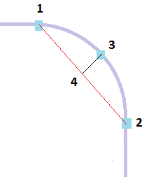
| Ratio of maximum chord height to chord length | Straight beams are used to emulate all of the curve. When a curve bends, applying an edge length that is suitable for straight section of a feed system could result in an inaccurate representation of the turn.
To allow ensure an appropriate edge length is applied, the cord height (distance 3 to 4 in the following diagram) is divided by the chord length (distance 1 to 2). The default value for this ratio is 0.05 with an available range of 0.02 to 0.3. Shortening the edge length will reduce the chord height and so reduce this ratio.
|
| Minimum number of elements on each curve for baffles and bubblers | This value corresponds to the minimum number of beams elements that need to be created on the sections of the curve that represents the baffles and bubblers. 3 beam elements is the default and minimum value, and can be adjusted in integer steps between 3 and 50. |
CAD tab
| Widget | Explanation |
|---|---|
| Use auto sizing | Check this option to automatically set the edge length and chord angle based on the dimensions and curvature.
Note: The global edge length defined in the
General Tab do not apply when this option is checked.
|
| Scale factor | Allows you to adjust the size of the mesh elements generated with the Use auto sizing by applying a scale factor. |
| Use global parameters | Check to use the global edge length defined in the General Tab. |
| Chord Angle | When selected, you can control the mesh density of curved features of the model by defining a chord angle. |
| Contact interfaces | There are three options that can be used for meshing assembly contact faces.
|
NURBS tab
| Widget | Explanation |
|---|---|
| NURBS surface mesher | Advancing Front Method used for mold meshing. |
| Enable chord height control | Increases the chance of creating a mesh that closely corresponds to curved surfaces.
Without chord height control, some surface curves, such as fillets, degrade when meshed. Chord height control is effective only with parts that have curved surfaces. Tip:
|
| Optimize aspect ratio by surface curvature control | Adjusts the size of the mesh to the local curvature on NURBS surfaces automatically. |
| Optimize aspect ratio by proximity control | Detects the proximity of boundary curves automatically, and ensures adequate mesh refinement at locations where boundaries are close to one another. |
| Smooth mesh (NURBS surfaces only) | Allows you to smooth the edges of a Midplane mesh. |
| Merge tolerance | Sets the minimum distance between nodes that will be targeted when generating the mesh.
If adjacent nodes are closer than this distance, these nodes will be merged together during mesh creation. |
Tetra tab
| Widget | Explanation |
|---|---|
| Minimum number of layers between external and internal mold surfaces | Specify the minimum number of layers you would like through the mold. The more layers you specify, the more accurate the temperature, but the longer the analysis will take. The default is 6 layers |
| Mesh size gradation ratio from surface to interior regions | Specify the change in size of the mesh as a ratio, from the coarser (larger mesh) outside surface, to the finer (smaller mesh) inside surface. The default is 1.3 |
| Maximum allowed edge length through thickness near external surface (Mold Surface wizard only) | Specify the maximum edge length near, and perpendicular to, the external mold surface. This determines the coarseness of the mold mesh. The mesh size will gradually change from this value to the value specified for the edge length near, and perpendicular to, the internal mold surface. |
| Maximum allowed edge length through thickness near internal surface (Mold Surface wizard only) | Specify the maximum edge length near, and perpendicular to, the internal mold surface. This value should always be less than or equal to the specified maximum edge length near, and perpendicular to, the external mold surface. |
| Maximum allowed edge length through thickness (CAD/STL mold only) | Specify the maximum edge length through the mold, to determine the coarseness of the mold mesh. |
| Ratio of first element layer thickness to local surface edge length | Specify the skin thickness in comparison to the surface edge length. A gradation applies automatically for the next layers. The default value is 0.8 |
| Number of enhancement layers on mold blocks and mold inserts (Induction Heating only) | Specify the number of extra layers created inside each layer.
Note: Check
Meshing guidelines for Induction Heating for more information on the recommended values.
|
| Scale factor to the thickness of enhancement layers (Induction Heating only) | Adjust the enhancement layer thickness. Default value is 1 |