You can customize the user interface to suit your needs. Most of the tools you need to do this can be found in the Option dialog. To access the Options dialog, click  ().
().
1. Customizable colors
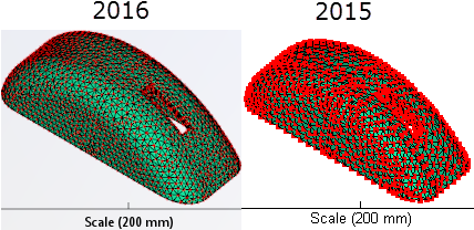
The background has been refreshed to give the canvas a more modern look and additional color tools have been provided so you can optimize your experience.
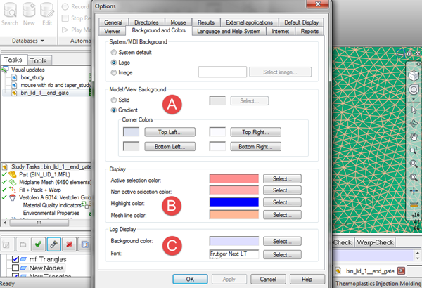
- A. Model/View Background
- The old-style blue gradient has been eliminated and replaced with a white background. All the color option tools can be found in the Options dialog. Click () and select the Background and Colors tab.
Select Solid if you want a single colored background, or Gradient if you prefer a color scale. You can select from the standard color palette, or create your own color palette.
- B. Display
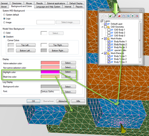
- A new entry, Mesh line color, has been added to the Display section. With this tool, you can change the color of your mesh lines to alter their contrast against your imported model color. Use this, in conjunction with the Highlight color option, to clearly visualize the various parts of the model and where they reside in the layers panel.
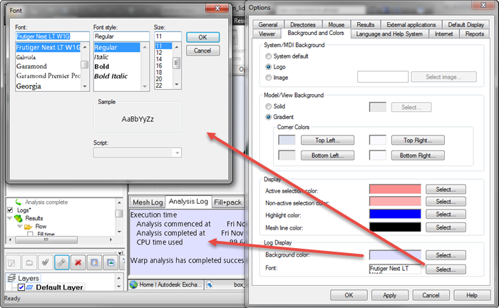
- C. Log Display
- The analysis log section below the model canvas has been updated, to provide you with options to customize its appearance. You can change the following items:
- Background color
- Font
2. Additional UI toggles
If you are particularly interested in maximizing the model pane real estate so that you can see the detail of the model more clearly, you can toggle various user interface items on and off from the View tab. Click  () and select or deselect items as desired.
In addition to the items that have been available in this toggle menu for many releases, the following new items have been added:
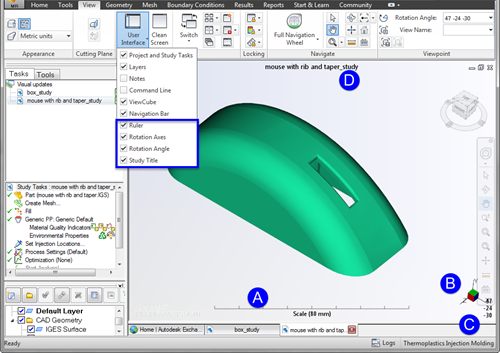
- A. Ruler
- B. Rotation Axes - this has been moved away from the model toward the right hand edge of the model pane.
- C. Rotation Angle - this has been moved to the bottom right hand corner, below the rotation axes.
- D. Study name - the study name can now be shown above the model. This is particularly helpful if you are working with several studies at the same time, to help you keep track of which one is active in the window.
3. CAD color imported from CAD program
With this release, the CAD model components are now be imported with the same colors they had when they were modeled in the CAD program. Hot runners and cooling channels are imported with the Moldflow default color. If a layer contains more than one CAD model, then the CAD color of the first CAD model is used for all CAD models in the layer.
To select the original color of the CAD model,
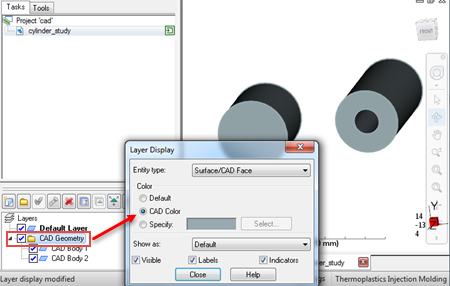
- Click on the CAD Geometry folder in the Layers panel, or whichever folder contains your CAD model, using the right mouse button.
- Select Display from the drop-down menu.
- Click CAD Color, then click Close.
4. Node display
As you zoom in and out of your model, the node size now increases and decreases relative to the model size, to enable you to see the model more clearly.