To make it easier to identify the type and location of some boundary conditions, glyphs have been created to show you what the boundary condition is, and where it is located.
Boundary conditions with new glyphs:
- Cooling inlets/outlets
- Valve gates
The glyphs are on, by default. To turn them off:
- Hover over the layer containing the glyph and click the right mouse button.
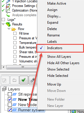
- Uncheck Indicators.
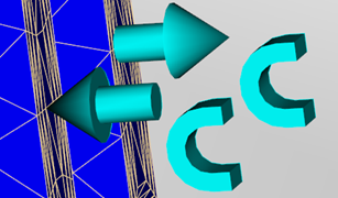
Valve gates
The valve gate glyph is easy to recognize as such, because it looks like a valve gate. Each valve gate glyph is named according to the valve gate controller name you gave it when you were programming it. As a result, you can tell at a glance which valve gate controller is being used at which location. The glyphs are visible while you are looking at the model. If you select a result to look at, then the glyphs disappear.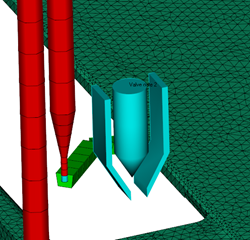
Cooling inlets/outlets
The coolant inlet and outlet glyphs now include a 'c' for 'coolant' to distinguish them from other inlet and outlet glyphs.