Apply conditions to improve the accuracy of simulations.
This video discusses how to assign thermal and mechanical boundary conditions to the build plate and how to improve the accuracy of your simulation by accounting for trapped powder.
Video length (4:53).
Follow the step-by-step instructions shown in the video. Sample files for use with the tutorials are available on the Download Page.
Assigning thermal and mechanical boundary conditions
- Click
, browse to the sample files for tutorials, and in the folder for Example_5, open
Example_5.tivus.
- Click
.
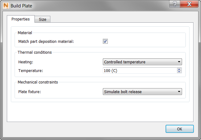
Note the Heating options available here:
- None initializes the build plate at the ambient temperature.
- Initial Temperature assigns the specified temperature at the start of the build, but does not maintain that temperature during processing.
- Controlled Temperature maintains a set temperature throughout the simulated build process.
- Set the Heating value to Controlled temperature, and Temperature to 100.
- Set
Fixture to
Simulate bolt release.
Fixture controls the mechanical boundary conditions. There are 2 options:
- Fix the bottom of the build plate fixes nodes on the base of the build plate, at the center of the build plate in X, Y, and Z directions, and constrains all other nodes in the Z direction.
- Simulate bolt release is used to model the construction of full build plates. It simulates the effect of bolting down each corner of the build plate for the deposition process, then allowing the part to cool down to room temperature, and unbolting the build plate, allowing the build plate to distort. It is used for this particular example to show what effect this option has on the simulation results.
- Click OK to close the Build Plate dialog, and then click Solve. When the simulation is finished, load the results.
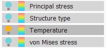
- In the Browser, turn on the
Temperature results and play through the animation.
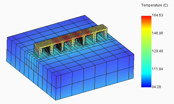
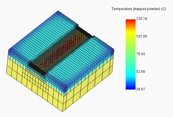
Accounting for trapped powder
By default, the thermal boundary condition is a static uniform heat flux on the surfaces of the component and build plate. For components that are closely packed together or have hollow walls or similar features where significant heat can be transferred through the powder, the model accuracy can be improved by modeling the powder directly.
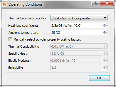
- On the
Home tab, click
Operating Conditions, and set the
Thermal boundary condition to
Conduction to loose powder.
- Click Solve to re-run the simulation, and import the results.
This time, play through the Temperature (trapped powder) results, to observe the effect of including powder elements during processing.