Import
New
Start a new simulation. This brings up the splash screen menu presented when Simulation Utility is originally opened.
Open
Open a .tivus project file. TIVUS files will save the geometry files, PRM files, and analysis settings. TIVUS files do not contain the log files or results files.

Import 3D CAD or STL files, such as one exported from Netfabb, to provide the geometry for parts and support structures in a simulation.
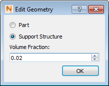
Users can use multiple STL part and support structure files on a single build plate. STL files containing zero thickness features are not compatible with the solver. When support structure STL files are imported, users must specify the volume fraction, which is used for homogenization of support structures. It is recommended that homogenized support structures be used instead of fine lattice structures to reduce both memory requirements and computational time.
Non-Homogenized versus Homogenized support structures
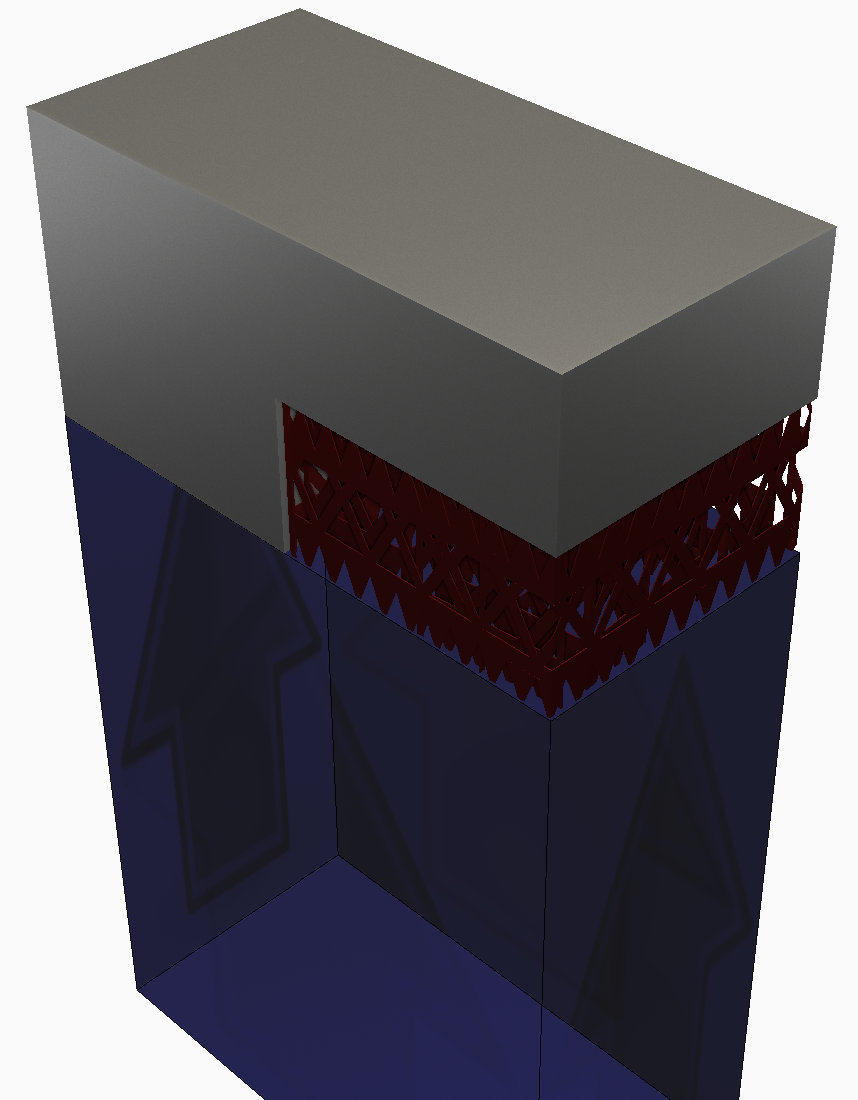
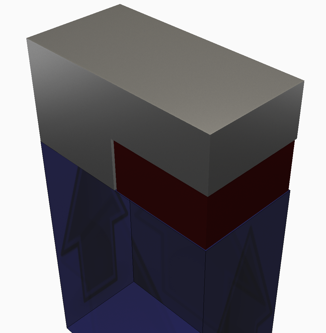
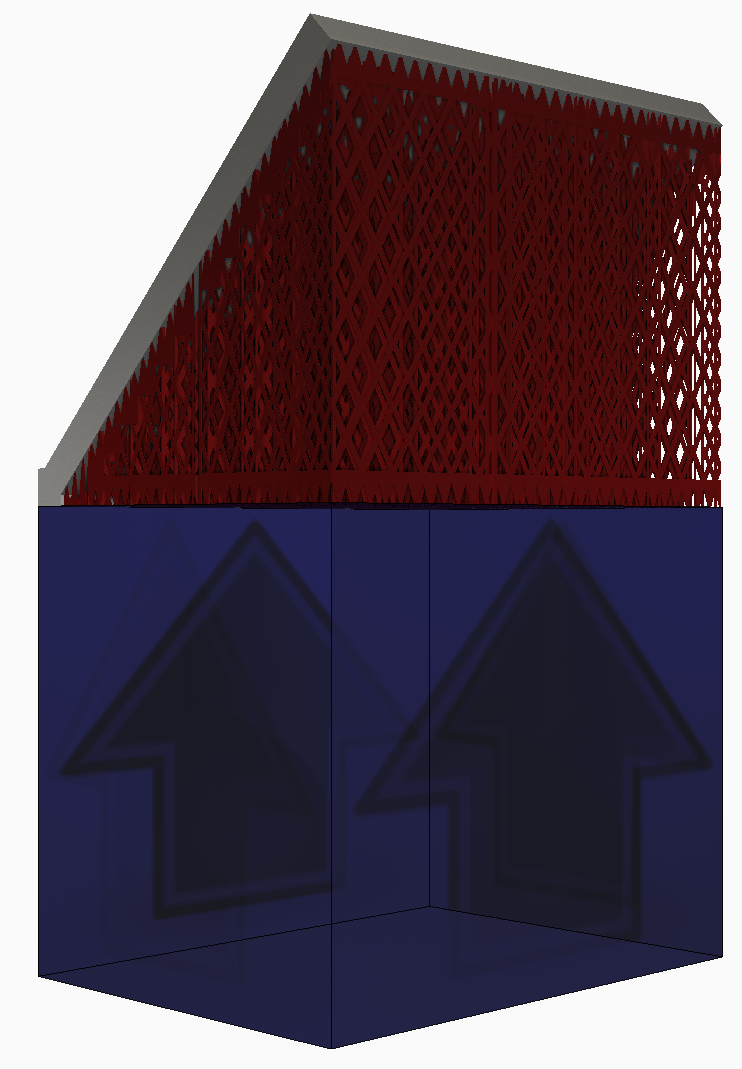
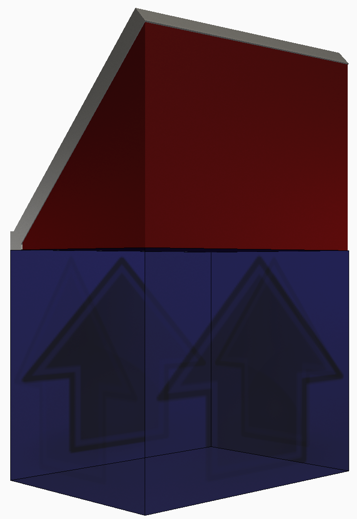
As shown below, while a fine, lattice type support structure with a thickness can be meshed and run, it is advised users implement the homogenization technique to reduce memory usage and simulation time. By default, upon import support structures are colored red.
|
|
| Non homogenized support structure | Homogenized support structure |
| Has material thickness | Has material thickness |
| Meshable | Meshable |
| Requires very fine mesh settings | Can use very coarse mesh settings |
| High memory consumption | Low memory consumption |
| Slower simulation | Faster simulation |
How to homogenize support structures
To homogenize a support structure:
- Create the supports, as built, using the material thickness of the support walls to ensure the ensuing STL or CAD file has a volume.
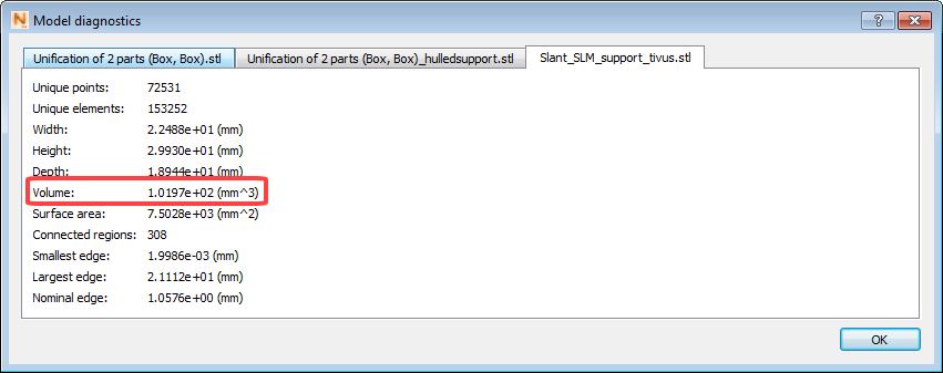
- Determine the volume of the original support structure. If the part has been imported into
Simulation Utility, this can be found by navigating to the file tree, right clicking on the part and choosing
Diagnostics from the drop-down menu. If there are multiple parts imported, select the tab corresponding to the correct part.
- Recreate the support structure but as a volumetric support structure, so that the support is a solid volume which occupies the same bounds as the original support.
- Determine the volume of the volumetric support structure.
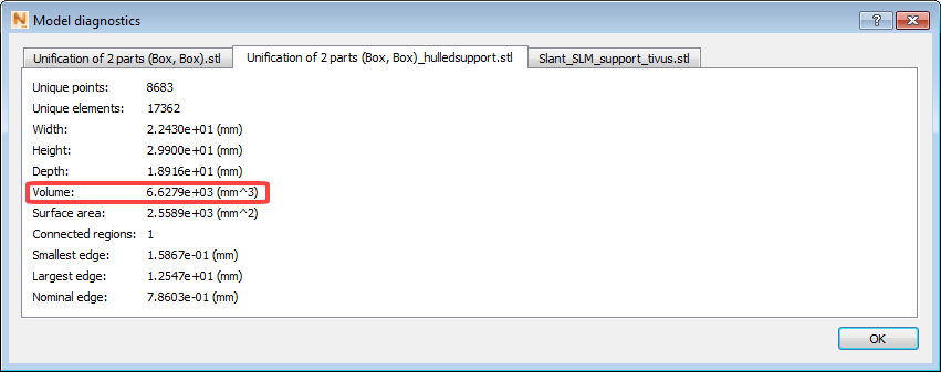
- Calculate the volume fraction: Volume fraction = Volume of original support structure/Volume of volumetric support. For this example the original volume is 102 mm³ and the homogenized support is 6630 mm³, which yields a volume fraction 0.0154.
- Import the volumetric support structure in Simulation Utility and when prompted, enter in the calculated volume fraction, rounded to the nearest hundredth.
About using PowerShape Utility and Netfabb
As stated above, if support structures are generated in Netfabb or PowerShape Utility, volume fraction is automatically calculated. When pushing parts and support structures from PowerShape Utility to the Simulation Utility, we recommend that users create fixtures from the Tree type or Extrusion: solid. Both of these support types are approved for simulation. Other fixtures can be sent to the Simulation Utility, but may not be properly meshed and simulated.
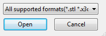
Simulation Utility supports more than 15 3D file types for the part model and the support structures. These are listed in the Supported File Types topic. In the Import model window, lower right corner, you can also click the ‘All supported formats’ list to see the supported format names and file extensions.
Save

Before running a simulation, click here to save your part file with the .tivus extension, specifying the name and location.
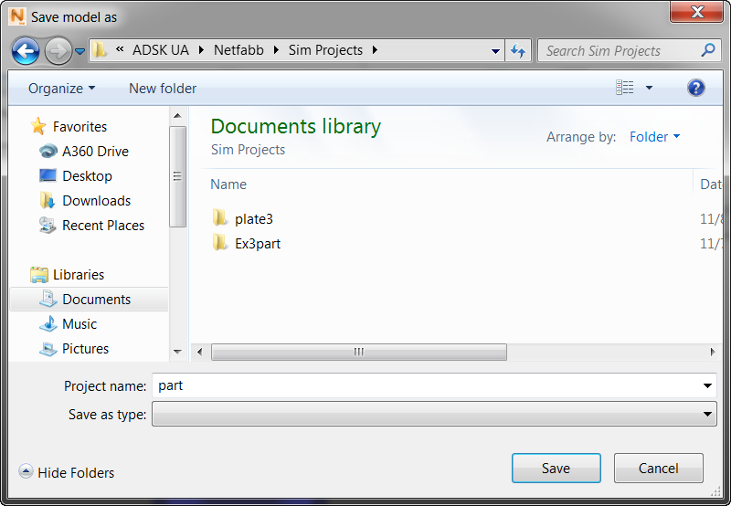
By default, the imported STL part name appears in the Project name field, and will be the name of the project folder, unless you decide to change it here. The model file (part.tivus in this example) is created inside the folder. When you run a simulation, related files will also be created inside the project folder. If you do not want to run the simulation now, you can do it later by clicking and selecting the saved TIVUS file.