Determine when deformation of the part is likely to interfere with the recoater blade.
This video discusses recoater blade interference; what it is, how it happens, and how it can be predicted with Simulation Utility.
Video length (5:49).
Follow the step-by-step instructions shown in the video. Sample files for use with the tutorials are available on the Download Page.
Recoater clearance is the percentage of the next powder layer that is not impinge upon by the upward deflection of the component. At 100% recoater clearance, the entire layer is undisturbed by the part. At 50%, the highest upward distortion of the part goes halfway into the next layer. If the recoater clearance drops too low, the recoater blade may impact the part, potentially damaging the component being built, the recoater blade, or both.
Recoater tolerance is a simulation control which specifies the amount of risk a user is willing to accept which performing simulations to predict recoater blade interference. This tolerance is the minimum percentage of the next powder layer the maximum upward deflection should not impinge upon, below which a warning will be issued by the simulation tool, and the binary recoater interference result, Recoater Status, is flagged as 1, indicating potential recoater problem. For example, using the default Recoater Tolerance of 80%, and a PRM file with a 0.040 mm layer thickness, if the maximum upward deflection past the nominal height predicted after any layer group at any point exceeds 20% of the next layer, or 0.0008 mm, the solver will issue a warning. For more information, see About Recoater Tolerance.
- Click .
- In the
Open model dialog, browse to the Example_7 folder and open the file
Example_7.tivus.
- On the Home tab, click Solve, and load the results when prompted.
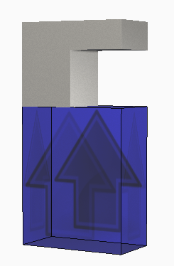
- On the Results tab, play through the animation, noting the upward deflection of the part as the overhang is built.
- To examine the deflection in more detail, click View Logs.
- Scroll to the bottom of the
Mechanical log to check for Warnings.
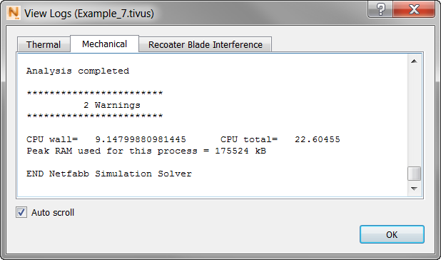
There are two in this case.
- Scroll up through the
Mechanical log to find the actual warning.
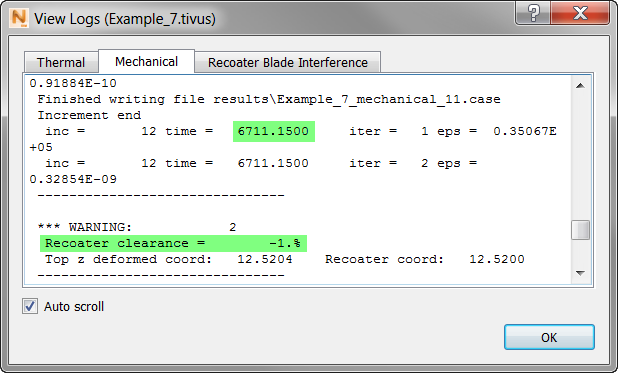
In this example, the warning occurred at 6711.15 seconds, when the recoater clearance was –1%.
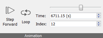
- To see this point in the animation, go to the
panel, and move the time slider to the time of 6711.15 seconds.
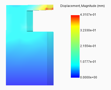
In the Displacement results at this time, you can see the upward deflection of the overhang.
You may also want to view the recoater clearance results:
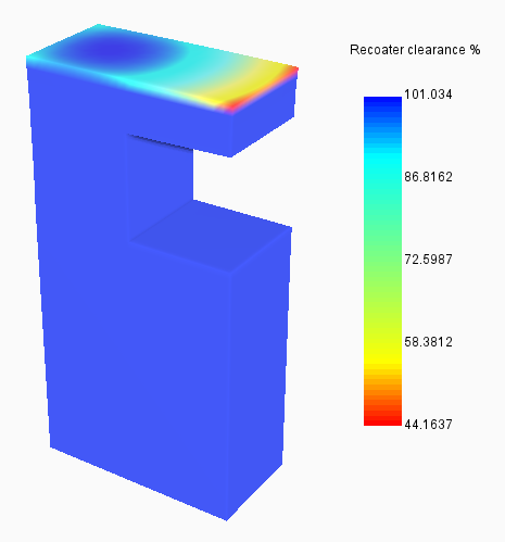
Note the inverted color spectrum in the legend for these results, reflecting the fact that high percentage values for recoater clearance are safe, while low values are risky.
Seeing clear evidence of interference, an engineer could decide to add support structures to prevent distortion of the part and damage to the recoater blade.