Results Display
Results are displayed, and updated in real time as necessary, in two locations: An Measurements tabsheet listing all available values pertaining to the currently performed, or currently selected measurement, as well as labeled representations in the content area. An additional display is available in the top-right of the display.
Reference Tools
The reference tools are a selection of shapes to select end points for measuring geometric properties. For each one, a selection of matching tools is available, and in combination, the type of measurement is selected.
| First tool | Details | Measurement Type |
|
|
This is a freely placeable reference location. It can go anywhere on a shell, provided the current Snapping settings allow the placement. |
|
|
|
Line specifies a straight edge no matter how many actual triangle edges form this edge. The specialty about Line is that it extends the edge as necessary, even beyond the actual edge of the triangles or parts involved. For instance, to determine the distance between a line and a point, the line is extended such that the perpendicular can be drawn through the point onto the line, with distance being the length of the perpendicular. Distance between two lines, however, also require them to be exactly parallel, otherwise the measurement will be labeled invalid. Extending the line also works for measuring Angles: The two edges do not have to actually form a common apex. They don't even have to be in the same plane. |
Angle Edge-YZ Plane Angle Edge-XZ Plane Angle Edge-XY Plane |
|
|
Netfabb attempts to determine circles by sampling a collection of possible "snappable" points and then checking whether circles can be drawn through them. As such, circles can be found where no full circle is available, such as by sampling curves of varying radii, or the circumference of a gear wheel formed only by its teeth. The center of the circle is available as reference. |
|
|
|
Specify a circle in 3D space by marking three points on parts anywhere in the build room. Its center will be used as the reference. |
|
|
|
Specify a sphere by marking three points on parts anywhere in the build room. Its center will be used as the reference. |
|
|
|
Specify a plane of contiguous triangles whose normals are also parallel. The surface formed, and its extension, is used as reference. |
Angle Surface-YZ Plane Angle Surface-XZ Plane Angle Surface-XY Plane |
|
|
This is a special selector that finds the distance to the nearest opposite part surface, drawn from the location of the selector and extended parallel to the negative normal of the triangle under the selector. At edges or corners, where multiple normals apply, moving the mouse around the point switches the selection between available normals. |
|
|
|
Specify three points to define an angle in the order of side, vertex, side. |
 Point
Point Distance Point-Edge
 Distance Point-Circle
 Distance Point-Circle
 Distance Point-Sphere
 Distance Point-Surface
 Wall Thickness
 3-Point Angle
Snapping
Snapping sets the mode of arresting point selection to the respective feature when you move the mouse pointer near them.
|
|
Snaps the point to the next valid feature in close vicinity. |
|
|
|
Just sets the point on the surface. |
|
|
|
Snaps the point to the nearest edge. Apart from that, it may move freely along the edge.
Note: It must be an actual edge. Triangles must meet with non-parallel normals here.
|
|
|
|
Snaps the point to the nearest node.
Note: It must be an actual corner. Triangles must meet with non-parallel normals here.
|
 Automatic snapping
 Free point
 Point on edge
 Point on node
Distance Measurement Options
With the toggles provide here, one for each of the cardinal axis, you select which component in 3D space to display in the label for the next measurement. This can also be changed individually for any existing measurements using the context menu of a measurement label in the display.
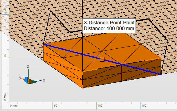
A diagonal measurement set to display the X component only.
Radius Measurement Options
This sets the default for further measurements: Toggle between the radius or the diameter of a circle or sphere to be measured and displaying in the label. This can also be changed individually for any existing measurements using the context menu of a measurement label in the display.