Autodesk® Netfabb® is a software application tailored for additive manufacturing, rapid prototyping, and 3D printing. It prepares three-dimensional files for printing and converts them into 2.5-dimensional slice files, consisting of a list of two-dimensional slice layers. To help users prepare the print, features are available for viewing, editing, repairing, and analyzing three-dimensional STL-files or slice-based files in various formats. To perform the print preparation operations, Netfabb uses an STL file format to create a mesh of the part.
STL files and triangle meshes
STL is the industrial standard for handling triangulated meshes. STL files contain a plain list of three-dimensional corner point coordinates and flat triangles. Triangles, also referred to as faces, are defined by three corner points and have an inside surface and an outside surface. Adjacent triangles may use common corner points and share the same edges, which results in a continuous triangle mesh. The generality and simplicity of this concept makes STL files compatible with many applications.
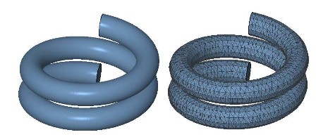
Parametric Surface and Triangulated Representation
However, STL files do not contain any topological information about the mesh. This causes typical errors when CAD files with different file formats are converted to STL. Netfabb can be used to detect and repair these kinds of damages and create faultless meshes without holes, deformations or intersections.
These meshes can then be converted into slice files ready for additive manufacturing. The STL format aims for a precise approximation of bodies in three-dimensional space. Although other CAD formats have advantages in that respect, a variety of applications need a surface representation consisting of flat triangles. These are:
- Rapid prototyping and additive manufacturing
- Accelerated rendering in multimedia applications
- Solving partial differential equations
- Computer Aided Design (CAD)
However, a simple collection of triangles will not always create a solid body. For a good triangle mesh that can be used for 3D printing, the mesh has to be valid, closed, oriented and should not contain any self-intersections.
Validity
Two edges of adjacent triangles which lie on top of each other are only regarded as one edge, if they have equal end points. Thus, the simple mesh below consists of two triangles and has exactly five edges: four border edges and one interior edge. Border edges belong to only one triangle, while interior edges connect two triangles.
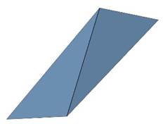
A simple mesh with 5 edges: four border edges and one interior edge.
A mesh is only regarded as valid, if interior edges have the same corner points for both adjacent triangles. Only then, all neighboring triangles are connected by a whole interior edge. No neighboring triangles are split and a smooth topology is created.
This validity is an essential property of most calculations. If two edges have only one common corner point, they will be defined as two border edges, even if they are on top of each other.
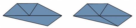
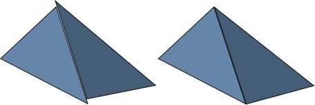
An invalid triangulation (left) compared to a valid triangulation (right).
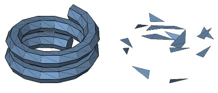
Two meshes, one valid and one arbitrary chaotic.
Closedness
Parts can only be used for 3D printing when their surface is closed. This means that there are no holes and no border edges. Every edge has to be attached to exactly two triangles and all neighboring triangles have to share an interior edge. Closedness may separate a mesh into several components called shells.
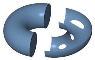
A closed surface (left) and a surface with holes (right)
Two disconnected (left) and two connected triangles (right)
Orientability
For the conversion of triangle meshes into slice data ready for 3D printing, it is vital that the parts are oriented correctly. The orientation defines the outside and the inside of a part.
The orientation of a part is determined by the orientation of all triangles. The order of the points defining a triangle defines its orientation by the right-hand rule. If the orientations of all neighboring triangles conform to each other and there are no flipped triangles, a closed shell separates outside from inside. But if there are flipped triangles, this might not be possible. Thus, even closed parts may be faulty.
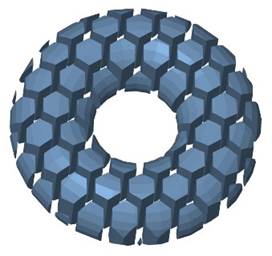
A mesh consisting of 60 disjoint shells.
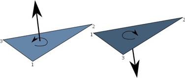
The orientation of a triangle is determined by the order of its points.
Self-Intersections
The surface of a solid body must not contain any self-intersections. These occur whenever triangles or surfaces of one part cut through each other. For many applications, self-intersections are very impractical, especially if the mesh shall be processed further.
For most additive fabrication processes, three-dimensional data has to be converted into 2.5-dimensional slice data. Here, self-intersections in the original data result in self-intersection in the slices. These might cause constructional failures or instabilities. Therefore, it is essential to remove self-intersections during the preparation of files.
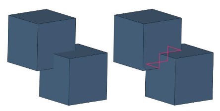
Self-Intersection: The two cubic shells cutting through each other
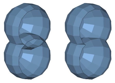
Left: A mesh consisting of two shells with self-intersection. Right: A mesh consisting of one, non-intersecting shell.