Topological Design Variable
Description: Defines a topology design region for topology optimization.
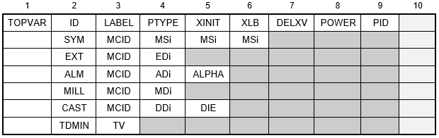
Format:
Example:

| Field | Definition | Type | Default |
|---|---|---|---|
| ID | Topology design region identification number. | Integer > 0 | Required |
| LABEL | Label associated with design region used for output headings. | Character | |
| PTYPE | Property type. Used with PID to identify the elements to be designed, one of the following character variables: PSOLID, PSHELL, or PCOMP. | Character | Required |
| XINIT | Initial value for design variable. Typically XINIT is defined to match the mass target constraint, so the initial design does not have violated constraints. | XLB ≤ XINIT | 0.5 |
| XLB | Lower bound for design variable to prevent the singularity of the stiffness matrix. | Real > 0.0 | 1.0E-03 |
| DELXV | Fractional change allowed for the design variable during design iteration. See Remark 2. | Real > 0.0 | 0.2 |
| POWER | A penalty factor used in the relation between topology design variables and element Young's modulus. The range between 2.0 ≤ POWER ≤ 5.0 is recommended. See Remark 2. | Real > 1.0 | See Remark 3. |
| PID | Property identification number. Must be unique with respect to the PID values specified in other TOPVAR entries as design regions cannot share the same element. | Integer > 0 | Required |
| MCID | Coordinate system identification number used to define manufacturing constraints. See Remark 4. | Integer > 0 or blank | 0 |
| MSi | Mirror symmetry planes, one of the following character variables: XY, YZ, or ZX. See Remark 4. | Character | Required |
| EXT | Symbol indicating that this line defines extrusion constraints (i.e., enforced constant cross-section) | Character | |
| EDi | Extrusion direction, one of the following character variables: X, Y, Z, -X, -Y, -Z, +X, +Y, +Z, where -X, -Y, -Z indicates the opposite direction of X, Y, Z and +X, +Y, +Z the same direction. See Remarks 4, 5, and 6. | Character | Required |
| TDMIN | Symbol indicating that minimum member size is specified. | Character | |
| TV | Minimum member size. See Remark 6. | Character | Required |
| ALM | Symbol indicating that this line defines additive layer manufacturing constraints. See Remark 7. | Character | |
| ADi | Print direction, one of the following character variables: X, Y, Z, -X, -Y, -Z, +X, +Y, +Z, where -X, -Y, -Z indicates the opposite direction of X, Y, Z and +X ,+Y, +Z the same direction. See Remarks 4 and 5. | Character | Required |
| ALPHA | Maximum overhang angle (measured in degrees). | Real | 45.0 |
| MILL | Symbol indicating that this line defines milling manufacturing constraints. See Remark 7. | Character | |
| MDi | Milling direction, one of the following character variables: X, Y, Z, -X, -Y, -Z, +X, +Y, +Z, where -X, -Y, -Z indicates the opposite direction of X, Y, Z and +X ,+Y, +Z the same direction. See Remarks 4 and 5. | Character | Required |
| CAST | Symbol indicating that this line defines casting constraints (i.e., die draw direction constraints). See Remarks 7, 8, and 9. | Character | |
| DDi | Draw direction, one of the following character variables: X, Y, Z, -X, -Y, -Z, +X, +Y, +Z, where -X, -Y, -Z indicates the opposite direction of X, Y, Z and +X ,+Y, +Z the same direction. See Remarks 4 and 5. | Character | |
| DIE | Die option selected by on of the following values:
When a single die is specified, the die slides in the given draw direction (i.e., material grows from the bottom in the draw direction). When two dies are specified the dies split apart along the draw direction (i.e., material grows from the splitting plane in opposite direction along the axis specified by the draw direction DDi). |
Blank or Integer 1 or 2 | 1 |
| SYM | Symbol indicating that this line defines symmetry constraints. | Character |
Remarks:
- The topologically designable element properties include PSHELL, PCOMP, and PSOLID. Multiple TOPVAR entries are allowed in a single file. Those elements whose PID is not specified in TOPVAR entries are considered to be non-designable elements; that is, they are considered to be fully filled by the material and are not changed during topology optimization.
- When X is the topology design variable of an element, the Young's modulus of the element is calculated by:

where,
E0 is Young's modulus of the material.
- A blank in field 8 uses an initial value for POWER of 1.0 and then increments POWER by 0.1 each design iteration to a maximum value of 4.0.
- One, two, or three different mirror symmetry planes can be present (such as MS1 = XY, MS2 = YZ, and MS3 = ZX). When the mesh is regular and parallel to the coordinate system MCID, all elements on the positive coordinate side are considered to have independent design variables, and elements on the negative side are considered dependent design. When the mesh is not regular or not parallel to the coordinate system MCID, an element in the negative coordinate side is considered dependent if the element is moved to the mirror plane and if there is an independent element on the positive side within the distance specified by the model parameter TOPTELEMSYMTOL (see Section 5, Parameters, for more information on TOPTELEMSYMTOL).
- Some symmetry constraint types can be combined with extrusion, casting, milling, and additive manufacturing constraints. The referenced coordinate system CID must be the same for the combined constraints. For example with extrusion, some possible combinations are: (EDi = X, MSi = XY, and/or ZX), (EDi = Y, MSi = YZ, and/or XY), (EDi = Z, MSi = ZX, and/or YZ).
- TDMIN is a dimensional quantity with a guideline that it be set to at least three times a representative element dimension. Without a TDMIN continuation line, the minimum member size is set to 3 levels of adjacent elements. Minimum member size constraints can be used with all other manufacturing constraint types.
- Casting, milling, and additive manufacturing constraints cannot be combined with extrusion constraints for the same TOPVAR entry.
- For two dies option (DIE= 2), the splitting plane is the surface closest to origin of MCID. For a single die (DIE = 1), the parting plane is the bottom surface of the designed part in the draw direction.
- It is recommended to use a smooth top surface in the draw direction for one die casting constraints, and smooth top and bottom surfaces in the draw direction for two die casting constraints.