Block specifies the shape, size and orientation of the raw material.
This displays the same options as the Blockdialog from the Home tab.
Defined by — Select an option to specify how to define the block. There are several ways of defining the block:
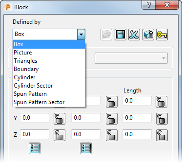
Box — Use this option when the raw material is a rectangular block that can be defined by minimum and maximum X, Y, Z points.
- Select Box
- If you need to change the size, edit the X, Y, and Z values.
- Click Calculate.
For example, if you enter an Expansion value of 15 before you click Calculate, PowerMill offsets the block by 15 mm from the minimum block size to enclose the model.
Picture — Use this option when the raw material is an extrusion that can be defined by a 2D contour (a cylindrical bar or pre-drawn billet). The contour must be saved as a .pic (DUCT picture file). The 2D picture must form a closed contour and not intersect itself (or any other contour).
- Select Picture.
- Click Load
 . This displays the Open Block from Picture, which enables you to open an existing picture file.
 - Click Calculate to automatically determine the length of the extrusion.
- If you need to edit the extrusion length, enter Min Z, Max Z and Length Z values.
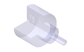
Triangles — Use this option when the raw material is a complex shape which can be defined by a 3D triangle model (a pre-cast block).
- Select Triangles.
- Click Load .
This displays the Open Block from Triangles dialog, which enables you to open an existing triangles file.
Boundary — Use this option for machining a specific area defined by an extruded 2D contour.
- Define the Boundary using the Boundary tab.
- Enter the extruded length in the Block dialog by either specifying a Min Z, Max Z, and Length Z or clicking the Calculate button.
Cylinder — Use this option when the raw material is cylindrical. The axis of the cylinder is along the Z axis.
Cylinder Sector — Use this option when the raw material is cylindrical and you want to machine a section of that cylinder.
Spun Pattern — Use this option to machine a part that is defined by a spun pattern.
Spun Pattern Sector — Use this option to machine a section of a part that is defined by a spun pattern
Load Block from File — Click to display either the Open Block from Picture or the Open Block from Triangles dialog. These dialogs enable you to open an existing picture or triangle file. You can click this button only if you select either the Triangles or Picture option from the Defined By list.
 Save Block —Click to save the block. This displays the Export Block dialog. You can save the block as a .dmt or .stl file.
 Delete Block — Click to delete the block.
 Lock all limits — Click this button to lock all the unlocked parameters.
 Unlock all limits — Click this button to unlock all the locked parameters.
Coordinate System — Select an option to lock the block to a workplane.
- Active Workplane — Select to lock the block's coordinates with the coordinates of the active workplane. If you change the active workplane, the block's size remains unchanged, but its orientation moves to reflect the new active workplane.
- Global Transform — Select to define the block's coordinates using the global coordinate system. The block's coordinates are then locked to the global coordinate system. If you change the active workplane, the block stays locked to the global transform, and its size and orientation remain unchanged.
- Named Workplane — Select to define the block's coordinates using the coordinates of a named workplane. If you change the active workplane, the block stays locked to the named workplane, and its size and orientation remain unchanged.
- To select a named workplane, click on the Workplane list and select a workplane.

If a block is locked to a named workplane, then you can move the block by moving the workplane.
This option is available only if you select the Named Workplane option on the Coordinate System list.
Limits — Enter the extents of the block. Select this option if the raw material is a rectangular block defined by minimum and maximum X, Y, Z values. You can enter the X, Y, Z values individually or click Calculate to calculate them automatically. If you enter a value of 15 in the Expansion field, this offsets the block by 15 mm from the minimum block size to just enclose the model. The X, Y, Z values are relative to the block's coordinate system.
You can lock specific X, Y or Z limits (Max, Min or Length) to prevent the value/s from being changed whilst adjusting the model limits.
 Unlocked — When displayed, you can edit the value.
 Locked — When displayed, you cannot edit the value. If you try to re-calculate the Block Limits by entering a specific or Expansion value, the Locked values remain unchanged.
- Click the button to toggle between Locked and Unlocked .
 — Click to display the Position dialog. Use the dialog to manually enter coordinates and locate items in the graphics window.
Cylinder Limits — Enter the extents of the block.
- The Calculate button automatically calculates the limit of the block to be just big enough to contain the entity selected in the Type field.
- Centre X — Enter the X coordinate of the centre of the circle defining the cylinder.
- Centre Y — Enter the Y coordinate of the centre of the circle defining the cylinder.
- Diameter — Enter the diameter of the circle defining the cylinder.
- Inner Diameter — Enter an inner diameter to create a hollow cylindrical block.
- Min — Enter the Z coordinate of the start of the block or calculate it automatically by clicking the Calculate button.
- Max — Enter the Z coordinate of the end of the block or calculate it automatically by clicking the Calculate button.
- Length — Enter the length of block in the Z axis or calculate it automatically by clicking the Calculate button.
- Unlocked — When displayed, you can edit the value.
- Locked — When displayed, you cannot edit the value. If you try to re-calculate the Block Limits by entering a specific or Expansion value, the Locked values remain unchanged. Click the button to toggle between Locked and Unlocked .
Sector Limits — Enter the angular extents of the block
- Azimuth start — Enter a value to specify the start of the azimuth angle range.
- Azimuth end — Enter a value to specify the end of the azimuth angle range.
- Range — Enter a value to specify the size of the azimuth angle range.
Estimate Limits — Use the fields to automatically calculate the extents of the block.
- Tolerance — Enter the tolerance used to create the block from the .dgk surface file.
- A small tolerance produces highly accurate results, but may take a long time to process; a large tolerance produces less precise results, but is quicker to process.
- Expansion — Enter the offset to the block from the minimum block size. If you are working with a surface file, however, you must also specify a Tolerance.
- Type — Select which entity is used when you calculate the limits.
- Include reference surfaces — Select to include the reference surface when estimating the block limits. This is useful when creating a surface projection toolpath where the reference surface is larger than the model.
- Calculate — Click to automatically calculate the limit of the block to be just big enough to contain the entity selected in the Type field.
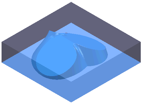
Draw — Select to display the block in the graphics window.
Opacity — Move the slider to control the opacity of the block. Move the slider to the left to decrease the opacity; move the slider to the right to increase the opacity.
Position the slider:
- to the extreme left, to draw the block as a wireframe.
- to the extreme right, to draw an opaque block.
- in the middle, to shade the block translucently, with translucency decreasing the further the slider is to the right.