The Definition tab on the Tool Axis dialog controls how you want the tool to orient itself whilst cutting a multi-axis toolpath. The default value is Vertical which is used for standard 3-axis machining.
This tab contains the following:
Tool axis — Select to define the tool orientation. The default value is Vertical, which is used for standard 3-axis machining. However, it can also be a fixed angle or a continuously changing orientation.
- Vertical — When selected, the tool remains aligned with the Z axis of the active workplane. This is the default value and is the value used for standard 3-axis machining.
- Lead/Lean — When selected, the tool is at a fixed angle relative to the Z axis of the active workplane. The tool is still dropped down the Z axis onto the model.
- Lead — Enter the tool angle, relative to Z, in the feed rate direction (the direction of travel).
- Lean — Enter the tool angle, relative to Z, perpendicular to the feed rate direction (the direction of travel).
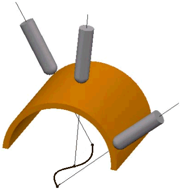
- Towards point — The tool tip tries to point towards the fixed point. The angle of the tool constantly changes. The head of the machine tool moves significantly, while the tip of the tool remains relatively still. This option orientates the tip of the tool towards a point.
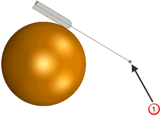
 User defined point. The tool axis always passes through this point.
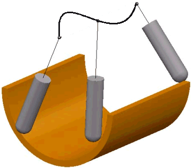
 - From point — The tool tip tries to point away from the fixed point. The angle of the tool constantly changes. The tip of the tool moves significantly, while the head of the machine tool remains relatively still. This option orientates the tip of the tool away from a point.
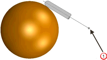 User defined point. The tool axis always passes through this point.
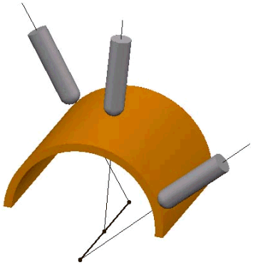
 - Towards line — When selected, the tool tip tries to point towards the fixed line. The angle of the tool constantly changes. The head of the machine tool moves significantly, while the tip of the tool remains relatively still. This option orientates the tip of the tool towards a line.
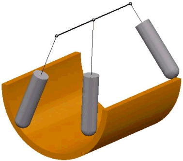
- From line — When selected, the tool tip tries to point away from the fixed line. The angle of the tool constantly changes. The tip of the tool moves significantly, while the head of the machine tool remains relatively still. This option orientates the tip of the tool away from a line.
- Towards curve — When selected, the tool tip tries to point towards the fixed curve. The curve must be a pattern with a single segment (selectable in the Pattern field). The angle of the tool constantly changes.
The head of the machine tool moves significantly while the tip of the tool remains relatively still. This option orientates the tip of the tool towards a curve.
- From Curve — When selected, the tool tip tries to point away from the fixed curve. The curve must be a pattern with a single segment (selectable in the Pattern field). The angle of the tool constantly changes.
The tip of the tool moves significantly while the head of the machine tool remains relatively still. This option orientates the tip of the tool away from a curve.
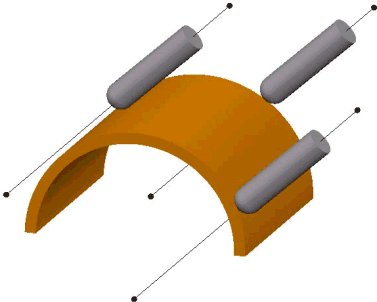
- Fixed Direction — When selected, the tool axis stays along the vector defined by the I, J, K vector. The tool axis is oriented in a fixed direction relative to the currently active workplane defined by a specified IJK vector. Although it can be difficult to work out the IJK vector, this option can enable you to machine undercut areas effectively. PowerMill first searches in the direction specified, and then, if that fails, searches in the opposite direction.
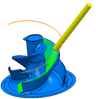
- Blisk — When selected you can apply the tool-axis orientation settings used to machine blisks and impellers to your preferred machining strategy. Use the Tool axis elevation area to specify the initial target tool axis:
- Radial vector — A radial tool axis, normal to the Z axis.
- Hub normal — The tool axis is normal to the hub. This gives a continuously changing elevation angle.
- Shroud normal — The tool axis is normal to the shroud. This gives a continuously changing elevation angle.
- Offset normal — The tool axis is normal to the current toolpath offset. This gives a continuously changing elevation angle.
- Average hub normal — The tool axis is the average angle if Hub normal was selected. This gives a continuously changing elevation angle. If possible, PowerMill will keep to this angle; otherwise PowerMill deviates as necessary.
- Average shroud normal — The tool axis is the average angle if Shroud normal was selected. This gives a continuously changing elevation angle. If possible, PowerMill will keep to this angle; otherwise PowerMill deviates as necessary.
- Average offset normal — The tool axis is the average angle if Offset normal was selected. This gives a continuously changing elevation angle. If possible, PowerMill will keep to this angle; otherwise PowerMill deviates as necessary.
- Angle — Enter the elevation angle. This option is available only if you select Radial vector in the From list.
Use the Blisk definition area to specify the Level or Set containing the reference surface:
- Shroud — Select the Level or Set that contains the Shroud surface.
- Hub — Select the Level or Set that contains the Hub surface.
- Automatic — When selected, PowerMill uses the geometry to determine the tool axis. This is useful for swarf and wireframe swarf machining where Automatic follows the surface rulings.
Pattern — Select the single segment pattern used to specify the curve when you use a Tool Axis of Towards Curve or From Curve.
 Create pattern — Click to create a new empty pattern.
 Selected pattern — Select a pattern from the list. If no pattern is displayed, or
  is selected, then no pattern is selected. The list contains a list of all available patterns.
 Curve Editor — Click to display the Curve Editor tab, which enables you to create and edit patterns. The assumption is that you first extract curves from the model, and then modify the curve to create the exact pattern you need.
 Select picked pattern — Click to select a pattern by picking in the graphics window.
 Collect curves — Click to copy the selected curves into the pattern.
Lead/Lean angles — Enter the angle of the tool from the vertical.
Mode — Select the reference direction for the tool axis from which PowerMill measures the lead and lean angles.
Point — Enter the fixed point location when using a Tool Axis of Towards Point, From Point, Towards Line or From Line.
 — Click to display the Position dialog. Use the dialog to manually enter coordinates and locate items in the graphics window.
Direction — Enter the orientation of the line from the fixed point when using a Tool Axis of Towards Line or From Line.
 — Click to display the Direction dialog, which enables you to edit the direction of an item.
Fixed angle — This fixes the tool axis azimuth or elevation angle to a specified value after the orientation has been calculated using the primary definition. This fixes one rotational axis of a machine tool wherever possible, giving a improved surface finish and increases the overall feed rate by reducing acceleration and deceleration. The locked axis is only overridden to avoid a collision and to ensure the tool stays on the part.
Tool Axis Limits — Select this option to enable the Limits page which controls angular limitations of the machine tool and so limits the angle of a tool while cutting a multi-axis toolpath.
Automatic Collision Avoidance — Select this option to enable the Collision avoidance page, which enables you to access 5-axis options that automatically tilts the tool axis, in a user defined way, to avoid collisions between the shank / holder of the tool assembly and the model. This only works when machining with the tip of the tool.
Tool axis smoothing — Select to display the Smoothing page. Use the function to smooth changes in velocity or direction of the tool axis.
Draw Tool Axis — Select this option to display the point or line used to define the tool axis in red. This is also available from Tool tab > Draw panel > Display > Tool Axis Definition.