3D Sketch
3D Sketch is used to edit a family or create a 3D object. In the Revit Platform API, you can complete the 3D Sketch using the following classes.
- Extrusion
- Revolution
- Blend
- Sweep
In other words, there are four operations through which a 2D model turns into a 3D model. For more details about sketching in 2D, refer to The 2D Sketch Class.
Extrusion
Revit uses extrusions to define 3D geometry for families. You create an extrusion by defining a 2D sketch on a plane; Revit then extrudes the sketch between a start and an end point.
Query the Extrusion Form object for a generic form to use in family modeling and massing. The Extrusion class has the following properties:
Table 40: Extrusion Properties
| Property | Description |
| ExtrusionStart | Returns the Extrusion Start point. It is a Double type. |
| ExtrusionEnd | Returns the Extrusion End point. It is a Double type. |
| Sketch | Returns the Extrusion Sketch. It contains a sketch plane and some curves. |
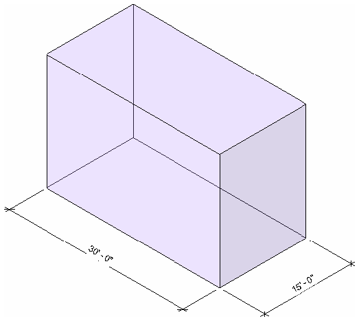 Figure 81: Extrusion result
Revolution
The Revolve command creates geometry that revolves around an axis. You can use the revolve command to create door knobs or other knobs on furniture, a dome roof, or columns.
Query the Revolution Form object for a generic form to use in family modeling and massing. The Revolution class has the following properties:
Table 41: Revolution Properties
| Property | Description |
| Axis | Returns the Axis. It is a ModelLine object. |
| EndAngle | Returns the End Angle. It is a Double type. |
| Sketch | Returns the Extrusion Sketch. It contains a SketchPlane and some curves. |
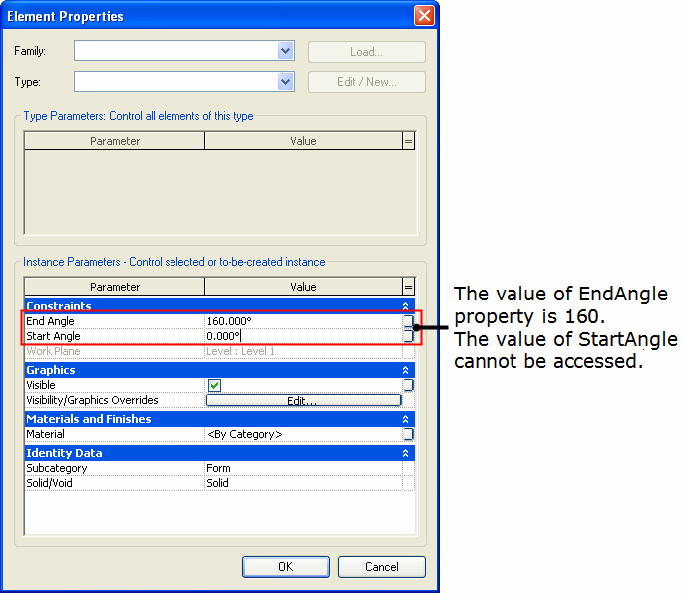 Figure 82: Corresponding parameter
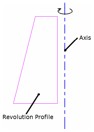 Figure 83: Revolution sketch
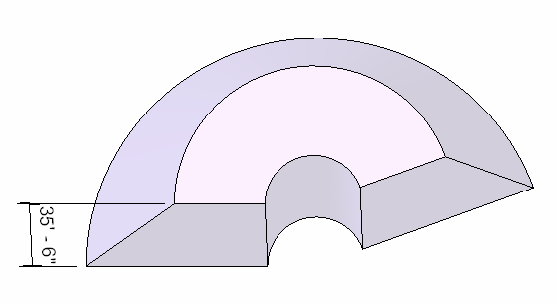 Figure 84: Revolution result
- The Start Angle is not accessible using the Revit Platform API.
- If the End Angle is positive, the Rotation direction is clockwise. If it is negative, the Rotation direction is counterclockwise
Blend
The Blend command blends two profiles together. For example, if you sketch a large rectangle and a smaller rectangle on top of it, Revit blends the two shapes together.
Query the Blend Form object for a generic form to use in family modeling and massing. The Blend class has the following properties:
Table 42: Blend Properties
| Property | Description |
| BottomSketch | Returns the Bottom Sketch. It is a Sketch object. |
| TopSketch | Returns the Top Sketch Blend. It is a Sketch object. |
| FirstEnd | Returns the First End. It is a Double type. |
| SecondEnd | Returns the Second End. It is a Double type. |
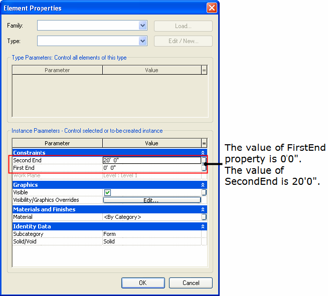 Figure 85: Blend parameters in the UI
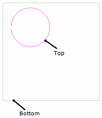 Figure 86: Blend top sketch and bottom sketch
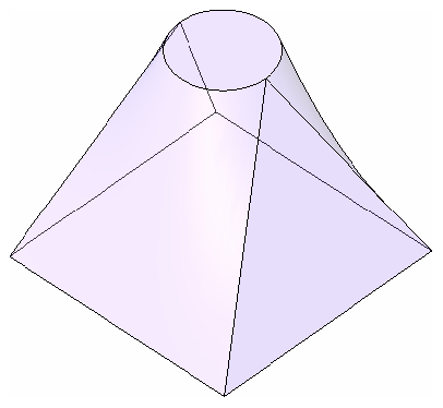 Figure 87: Blend result
Sweep
The Sweep command sweeps one profile along a created 2D path or selected 3D path. The path may be an open or closed loop, but must pierce the profile plane.
Query the Sweep Form object for a generic form for use in family modeling and massing. The Sweep class has the following properties:
Table 43: Sweep Properties
| Property | Description |
| Path3d | Returns the 3D Path Sketch. It is a Path3D object. |
| PathSketch | Returns the Plan Path Sketch. It is a Sketch object. |
| ProfileSketch | Returns the profile Sketch. It is a Sketch object. |
| EnableTrajSegmentation | Returns the Trajectory Segmentation state. It is a Boolean. |
| MaxSegmentAngle | Returns the Maximum Segment Angle. It is a Double type. |
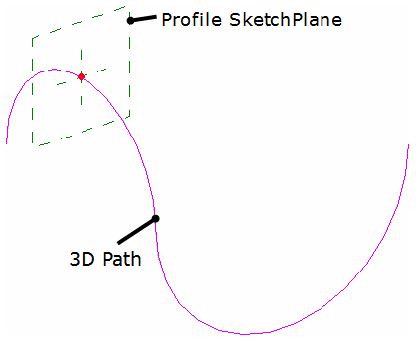 Figure 88: Pick the Sweep 3D path
- The Path3d property is available only when you use Pick Path to get the 3D path.
- PathSketch is available whether the path is 3D or 2D.
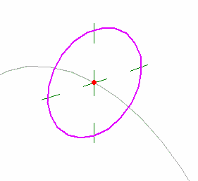 Figure 89: Sweep profile sketch
Segmented sweeps are useful for creating mechanical duct work elbows. Create a segmented sweep by setting two sweep parameters and sketching a path with arcs.
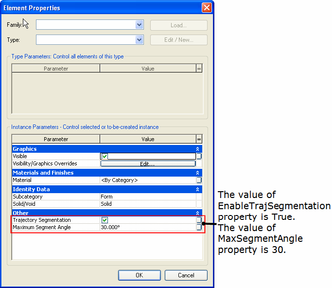 Figure 90: Corresponding segment settings in the UI
- The parameters affect only arcs in the path.
- The minimum number of segments for a sweep is two.
- Change a segmented sweep to a non-segmented sweep by clearing the Trajectory Segmentation check box. The EnableTrajSegmentation property returns false.
- If the EnableTrajSegmentation property is false, the value of MaxSegmentAngle is the default 360°.
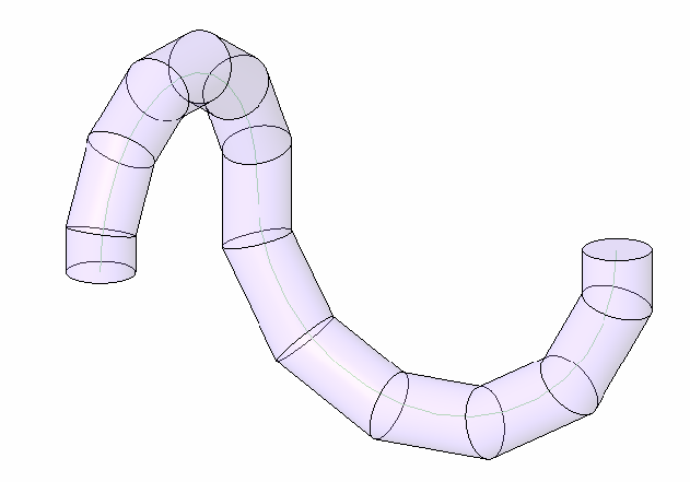 Figure 91: Sweep result