These examples describe families from simple to complex. Study these examples to learn how you can create families that meet the needs of your design.
For each sample family, click the RFA family name to download the file. Then you can examine the family to see how it is defined and how it works.
Simple Profile Family
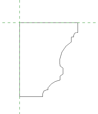
This profile shows an example of a simple 2D closed shape. After you load the family into a project, you can select this moulding profile to use it wherever a profile can be assigned, such as a wall sweep or in an in-place model with a sweep.
This profile family does not contain any constraints. The shape is static, and the family contains only one type.
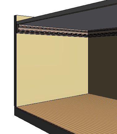
The moulding profile used for a wall sweep
Detail Component Family
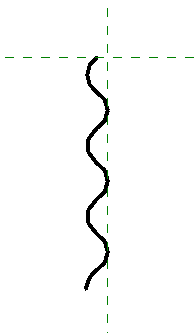
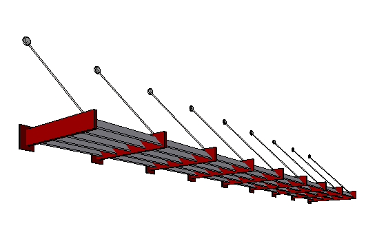
Detail component families are 2D families used in detail views to enhance or replace the model geometry of the project. The Corrugated_Metal sample family represents a section of corrugated siding material. The family consists of arc segments without any constraints for controlling the geometry.
The parameters of the family contain keynote information. If you use keynotes when annotating the project, the keynote is resolved when you place a keynote tag in a view.
If you need to place a detail element multiple times adjacent to one another, you can use a detail component family like this one to create a repeating detail.

Corrugated metal shown in a detail view
Generic Annotation Family (Key Plan)
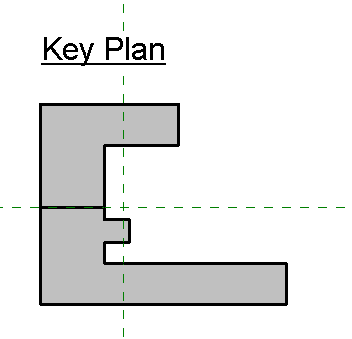
A key plan for a project is created with a generic annotation family. Place the generic annotation onto a sheet or a view where a key plan is needed. The example family contains lines making up the footprint of the building and filled regions connected to visibility parameters so the different shaded portions of the key plan can be turned on and off.
Two-Pick Family to Calculate Fire Exiting Distance
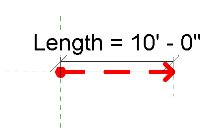
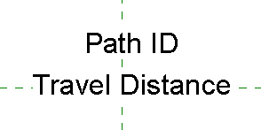
This travel line family is an example of a generic two-pick family. You place the travel line by selecting 2 points. The geometry is then placed along the line of the 2 picked points.
This family is designed to be used to calculate fire exiting distance. In a view, place a series of these elements along the fire exit route to represent the travel path. The family includes shared parameters for the travel distance and the path ID, which can be used in conjunction with tags and schedules to calculate the distance of all segments of the travel line in the exit path.
The family also includes visibility parameters to control the visibility of the dot at the beginning of the path and the arrow at the end. The visibility controls allow multiple segments placed end-to-end to appear to be one continuous path.
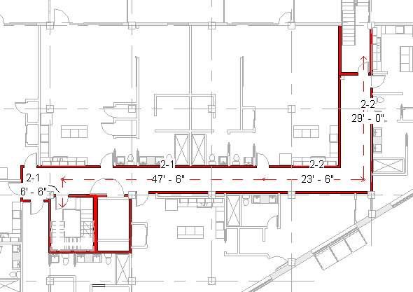
An exiting plan
Family for Tag Labels
The Exiting_Tag.rfa family is used in conjunction with the Travel_Line.rfa family. The tag family is composed of 2 labels that report the shared parameter values for the travel distance and the path ID of the travel line being tagged.
Enhanced Family with Constraints and Nested Elements
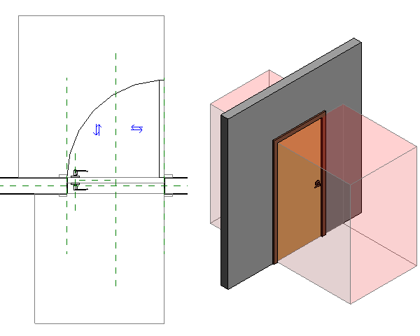
This sample door family makes modifications to an existing door family. Door clearances are established using symbolic lines, extrusions, and constraints, and door level hardware is added.
To establish door clearances, symbolic lines are placed in the plane representation of the door. The additional symbolic lines represent clearances for accessibility requirements in the United States. The lines are constrained to the door geometry so that, when the door size is changed, the clearances adjust to the new door size.
The symbolic lines use an invisible line style so they do not display when the door is placed in the project. However, the lines display when you move the cursor over the door or select the door in the project. In the 3D representation of the door, an extrusion is constrained to the accessibility clearance lines. This strategy allows you to use the Interference Checking tool to verify that all doors meet accessibility requirements.
To add hardware to the family, a family that defines the door lever geometry is added to the door family. The nested family uses a family parameter label, which allows the lever hardware to be swapped among 3 different styles. The lever handle families each have parameters connected to the door thickness so the position of the handles will change if the door thickness is changed. The handle visibility has been set so the door levers are not displayed in the plan view of a project or if the detail level of a view is set to coarse.
Advanced Two-Pick Family with Nested Elements and Formulas
The advanced sample family (available from the Recent Files window) is a two-pick family. It contains nested elements and uses formulas to drive the geometry of the family. For more information about this family and how it works, see Formula Examples.
