Assign a reference to which beam end geometry will align. The reference can fall along the geometry of linked beams, walls, and columns. Reference lines of beams and columns such as center lines or reference planes defined within a family.
Video: Beam Alignment References and Cutback
- Select either a beam or brace or use a pick box to select multiple elements.
- Click Modify | Structural Framing tab
 Modify End panel
 (Change Reference). If the Change Reference tool is unavailable, verify the following:
 - The Detail Level of the view cannot be set to Coarse
- All multiple selected elements must be joined to a common element.
- The element must be joined to another element
- The element must be linear and straight
- The element must not be concrete.
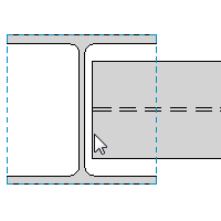
- Select a reference line or element geometry line edge to which the geometry will align. Tab select to access specific geometry lines of an element.
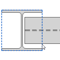
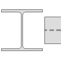
For this example, a beam attached to a column will be aligned to the web face of the column and overriding setback.
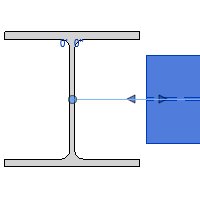
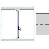
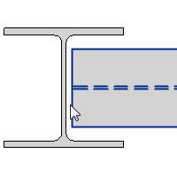
Likewise, you can choose reference lines and extents of other beams, columns, and walls.
Center of a concrete beam Center of a support column in an elevation Exterior face of a structural wall 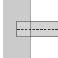
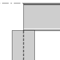
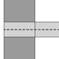
You can also align to non-perpendicular lines as shown.
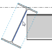
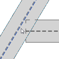
To remove the alignment reference
- Select the framing elements to be reset.
- Click Modify | Structural Framing tab
 Modify End panel
 (Change Reference).
 - Select any side of the bounding box of the column.
 |
 |
 |