Planes are great for showing a two-dimensional slice through the model, but the best information often comes in three dimensions. In this step, we create particle traces for a more complete view of the flow.
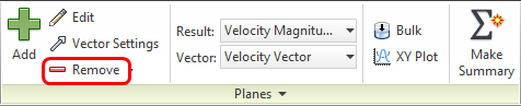
1. The next steps are easier if we delete the results plane. Click Remove on the Planes context panel:
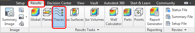
2. Click Traces from the Results tab:
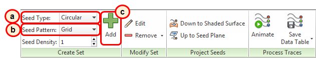
3. We can create traces on nearly any surface in the model, but the inlet is often the most convenient place. To create traces:
-
a. Set the Seed Type to Circular.
- b. Set the Seed Pattern to Grid.
-
c. Click Add.
4. To create the trace seed grid:
-
a. Click in the center of the inlet.
-
b. Drag the grid to the outer edge of the inlet.
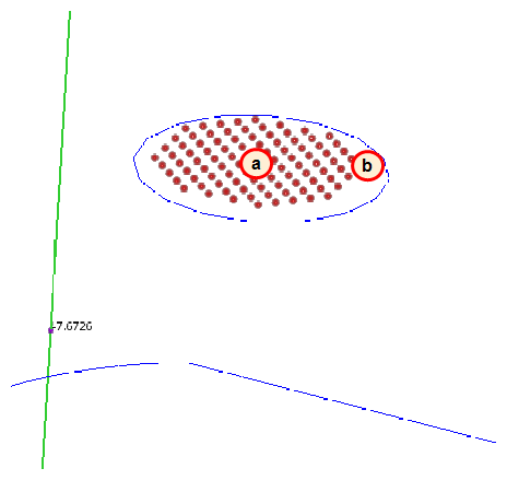
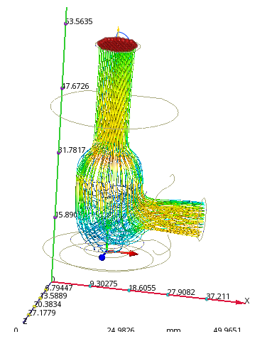
You should see this:
5. To display the pipe and poppet transparently:
-
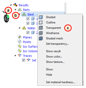
a. Expand the Parts branch (under Results) in the Design Study bar.
-
b. Right click on Steel.
-
c. Click Transparent.
-
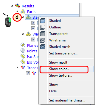
d. Right click on Steel again, and select Show color...
-
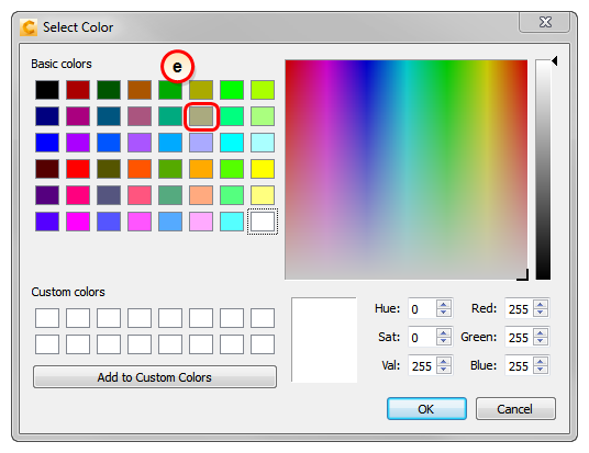
e. Select this color on the Select Color dialog, and click OK.
-
f. To see the traces better, right click on Steel again, and click Set Transparency. Drag the slider to 80%.
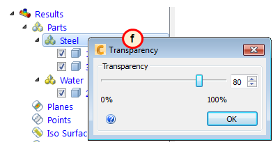
You should see this:
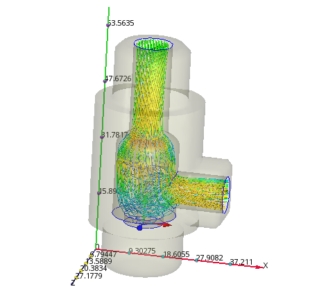
That's better! This helps us understand how the flow moves through the valve. The traces are colored by velocity magnitude, so we can also see how the flow accelerates as the water enters the outlet pipe.
Wrap up
In a few short minutes, you conducted a complete CFD simulation on a 3D valve model. You created views that are interesting and useful! You used vectors to see how the water flows through the pipe and around the poppet, you displayed the static pressure to see how much pressure the flow loses, and you used traces to create a three dimensional view of the flow.