In FeatureCAM, you can display the following types of simulation:
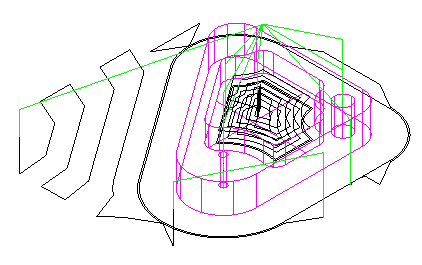
Centerline — Lines are drawn that represent the center of the tip of the tool. This simulation method is usually the fastest.
The default colors are:
|
|
Rapid moves (G0) |
|
|
Toolpath lines and arcs (G1, G2, G3) |
|
|
Index moves |
|
|
Part line program toolpaths |
|
|
Ramps and leads |


You can change these colors in the Default Colors dialog.
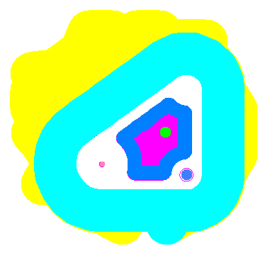
2D — For turning, this style shows a cross section of the part. For milling this style shows a flat (from the top) view of the part, with each tool being shown in a different color.
3D (sometimes called Visicut) — This style shows a three-dimensional shaded rendering of the initial stock and simulates material removal in 3D. You can optionally display the holder. Any gouge caused by holder interference or the tool hitting the part during a rapid move is displayed in pink. For turning simulation a 3/4 cut-away view is optionally available to view ID cuts.
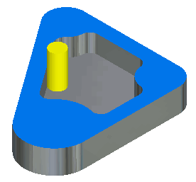
3D RapidCut — This shows a fast simulation of a 3-axis milling job. You can also use it with 2.5-axis milling, but it works best for 3-axis milling.
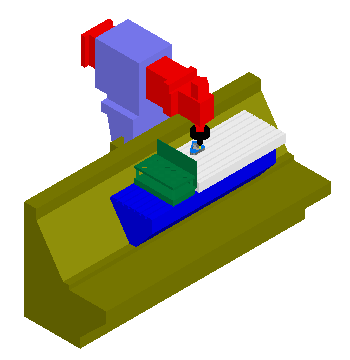
Machine simulation— This displays the motion of the entire machine tool.
With all simulation methods, video-style controls are used to pause, stop, and step through the toolpath, giving you fine control over the process.