The Drawing Management feature of AutoCAD Architecture toolset lets you create large building projects distributed among many drawing files.
Project
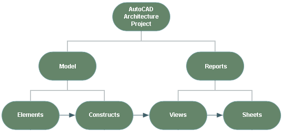
Constructs
A construct describes one unique portion of a building and is assigned to a specific level and division within the project. Spanning constructs, like curtain walls, can be assigned to multiple levels and divisions.
For example, the first level of your building project may consist of an exterior shell construct, a first-level core construct, and a first-level interior partitions construct.
A construct can contain drawing objects like walls and doors, external references to elements, or a combination of both. For example, a first-level core construct can contain the core walls directly drawn into the construct and an elevator element inserted as an external reference.
You can create and modify constructs within the current project. You can also import drawings and convert them or add them to constructs. You can import constructs into the project physically or by creating a link.
Constructs are referenced into views.
Views
After the structure of the building is defined, and constructs are assigned to levels and divisions, you can generate reports (views and sheets) from the building model. A view automatically references a number of constructs to present a specific view of the building project. To create a view drawing, you first decide what portion of the building you wish to look at and the type of view to generate. You could, for example, create a first-floor reflected ceiling plan or a second-floor framing plan.
You could also create a composite view of all floors in the building as shown:
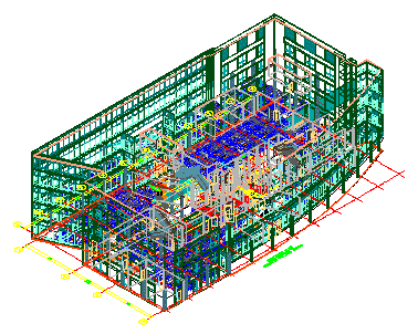
3D view of entire building view
View drawings automatically reference the appropriate constructs according to their location within the building. For example, to create a floor plan of the west wing of the second floor, you would create a view that references all constructs assigned to the second floor and the west wing. This would also include a curtain wall spanning the first through fifth floors. You can reference additional constructs that you want to see in the view even though they do not lie on that floor, such as a building outline.
In a view drawing you can also add data like annotation, dimensions, and schedules. Whether to create the annotation in a view drawing or on a sheet is a decision you make based on your workflow and individual needs.
Three different types of view drawings, each with its own template and identified by a different icon, can be used as organizational tools.
- General view drawing
- Detail view drawing
- Section/Elevation view drawing
Views are referenced into sheets.
Sheets
Sheets are used to plot drawings of your building project.
The sheet system in AutoCAD Architecture toolset consists of the following components:
- Sheet: A sheet is a paper space layout that has been registered as a sheet. A sheet can contain one or more sheet views.
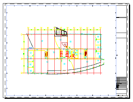
Sheet with building plan sheet view
- Sheet views: A sheet view is a paper space viewport created by dragging a model space view from a view drawing in the Drawing Explorer onto a sheet.
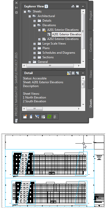
Sheet view created from model space view
- Sheet set: A sheet set is a named and ordered collection of sheets. Sheet sets are similar to the physical set of bound sheets that are the primary communication medium for a typical building project. Sheet sets are tailored for efficient output of printed or electronic documents through the Publish command.
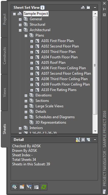
Sheet set for AutoCAD Architecture Toolset project
Each project in AutoCAD Architecture toolset has a simple project sheet set, which contains all sheets for the project.
- Sheet drawing: A sheet drawing is a DWG file containing one or more sheets.
Sheet set, sheets, sheet views, sheet drawings, and model space views are listed on the Sheets and Views tabs of the Project Navigator.
Although it is recommended to place annotation in a view, you can add annotation like tags, dimensions, and schedule tables to a sheet.
Project Standards
There is a Project Standards feature in AutoCAD Architecture toolset. Project standards provide a mechanism to establish, maintain, and synchronize styles and display settings across an AutoCAD Architecture toolset project. Within a project, you can specify standard styles, display settings, and AutoCAD standards that are used across all project drawings. Standard styles and display settings are defined in standards drawings associated with the project. The project is synchronized with these standards throughout the project life cycle.
Project Tool Palettes and Content Browser Library
In addition to standards drawings, you can also set up project-specific tool palettes and a Content Browser library for a project. A user-definable root path for tool content ensures that the tools always reference the correct content drawing for their definition.
External Reference Management
External references allow your source files to be distributed over many different locations on your computer or on a network. You can assign schedule tables, annotation tags, and dimensions to external references easily. Different people can work simultaneously on the same project.
You specify whether reference paths are full external or relative external paths.
Mapped Drives
AutoCAD Architecture toolset supports mapped drives within a project environment. You can map the same identifying drive letter on different servers with the same project structure. If you use mapped drives within an AutoCAD Architecture toolset project, you are not prompted to repath each time you open the project drawing files from different servers.
XML Structure
An AutoCAD Architecture toolset project has an underlying XML structure. For each drawing file you create—for example, a floor drawing or a structural drawing—an accompanying XML file is created. The XML file contains project-relevant information, such as level and division information. You can reuse any drawing file created within a project outside the project as well, because the drawing file itself does not contain project-relevant information.
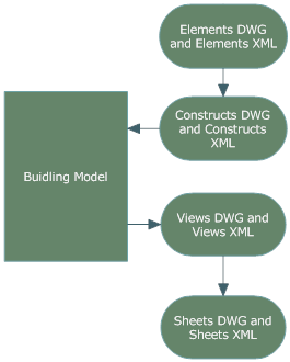
Levels and Divisions
The project provides a framework of levels (floors) and divisions (wings) that specify where in the building project constructs are located. By default, a new project consists of one level and one division. You can add levels and divisions throughout the lifetime of a project. The matrix of levels and divisions provide the framework to help uniquely identify the building components. For example, you could have a construct in your building assigned to First Floor—West Wing.
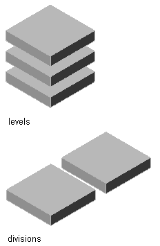
Levels and divisions schematic
Building objects, such as curtain walls and elevator shafts, can span multiple levels and divisions. You can use a spanning construct for these types of building objects.
Categories
To help organize the building, components of the building project—constructs, views, and sheets—can be categorized. You can use categories like shell, core, and interior partitions. Categorizing a construct lets you filter that construct when generating views.
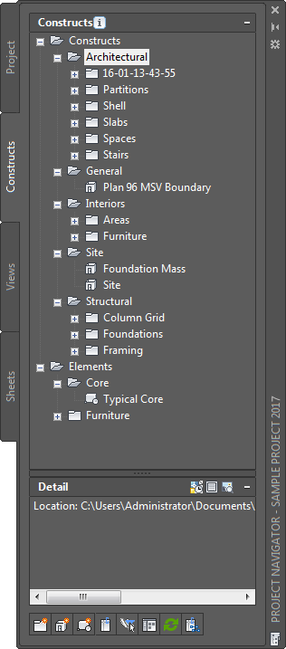
Construct categories in the Project Navigator