Learn the steps of drawing, defining and saving a user section.
Create a User Section
To access the command:
On the Objects tab  Beams panel, select
 (Other sections).
Command line: _astm4crbeambyclass A
To create a beam with User Section
- Select a suitable UCS.
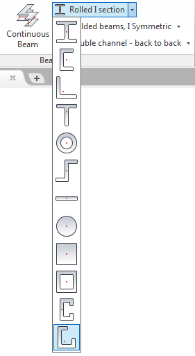
- On the Objects tab Beams panel, select
(Other sections) from the flyout:
- Specify the start point of the beam system axis.
- Specify the end point of the beam system axis and press Enter.
- The straight beam is created and the properties dialog box appears, where you can modify the properties.
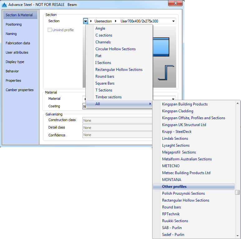
- From the Section drop-down list select the user section and the desired size.
Define a User Section
To define the User section in a separate DWG
- Open a new DWG file.
- Set the Top view from the AutoCAD Views panel.
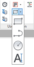
- On the Extended Modeling tab, User section panel, use the change layer flyout to activate the corresponding layer and the tools flyout to draw the section components.
Define a user section frame
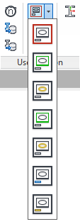
- On the change current layer flyout, click
 (Frame). The section frame layer is activated.
- On the tools flyout, click
 (Rectangle).
- Specify the first corner point of the frame.
- Specify the diagonal opposite corner of the frame.
Define a user section outer contour
- On the change current layer flyout, click
 (Outer contour). The section outer contour layer is activated.
- Using the tools on the tools flyout, draw the outer contour. It must be a closed polyline, a circle or a rectangle.
Define a user section inner contour
The inner contour is useful, for example, to create hollow sections.
- On the change current layer flyout, click
 (Inner contour). The section inner contour layer is activated.
- Using the tools on the tools flyout, define the inner contour inside the exact outer contour.
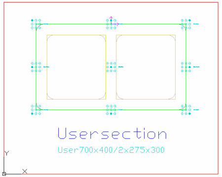
Define the user section class and name
- On the change current layer flyout, click
 (Section class) or
 (Section name). The text for the section class name will appear on the Section & Material tab in the Advance Properties dialog box.
- Using the tools on the tools flyout, select
 (Single Line Text) to define the desired texts.
Add system coordinates and reference axis
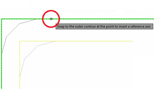
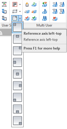
To define the coordinate system that represents the local axis select the outer contour. To access the Add coordinates command, select
 (Add coordinates) from the Extended Modeling tab, User Section panel.
For example, to position the reference axis in the top-left, select the command and when the "Snap on the outer contour at the point to insert a reference axis" message appears, click to place, using the snap points. If you do not click the point where the reference axis should be inserted, then the axis will be positioned where the point is selected on the outer contour.
Save a user section
Verify that all contours and the section properties are inside the frame.
To save the section, use one of the following methods:
- On the Extended Modeling tab User Section panel, click
 (Generate selected section).
- On the Extended Modeling tab User Section panel, click
 (Generate all sections).
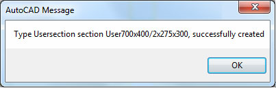
The following message confirms that the section was successfully created:
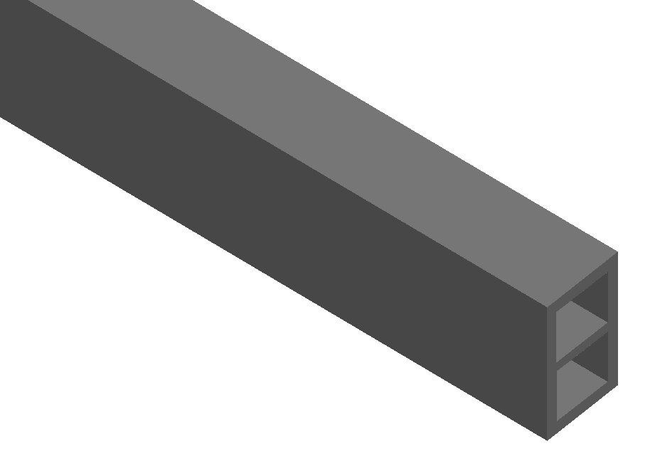
To draw the new user section, choose any profile from the menu and in the properties dialog box, in the Other profiles category, select the name of the user section class you created.