In this exercise, you use two of the correlation commands available in AutoCAD Raster Design toolset:
- Scale. Makes an image larger or smaller by specifying a known distance between two points on the image itself. Scale only performs the re-scaling about a specified base point, no rotation is involved.
-
Match. Aligns an image to existing vector linework by specifying two source points on the image and two destination points in the drawing. The image is rotated, scaled, and moved as necessary to match the source points to the destination points.
By correlating the image with the existing geometry before you make any design changes, you avoid perpetuating inconsistencies in scale and position when you modify the raster or vector data.
Related Exercises
Before doing this exercise, ensure that AutoCAD Raster Design toolset options are set as described in the exercise Exercise A1: Setting AutoCAD Raster Design Toolset Options.
Exercise
- In the \Tutorial4 folder, open the drawing file
Hybrid_02.dwg.
Scale the image
- View the current vector and raster linework in the drawing.
The linework in the image and in the drawing are not aligned.
- Click
View menu
 Named Views. Then expand the
Model Views list, and set the current view to
TU_scale.
Named Views. Then expand the
Model Views list, and set the current view to
TU_scale.
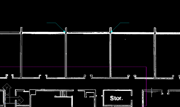
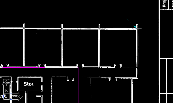
- Enter
dist (DISTANCE command) to determine the width of the center classroom, measuring from left to right.
The width of the classroom is approximately 34 feet (10.4 meters). It needs to be shown in the drawing as 25 feet (7.5 meters) instead.
This example shows the two points you select to measure the width of the center classroom.
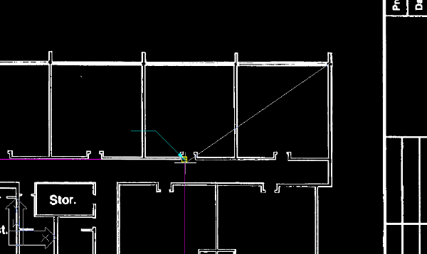
- Click
Raster menu CorrelateScale. Then select the intersection of the outside wall and the left wall of the center classroom for the base point.
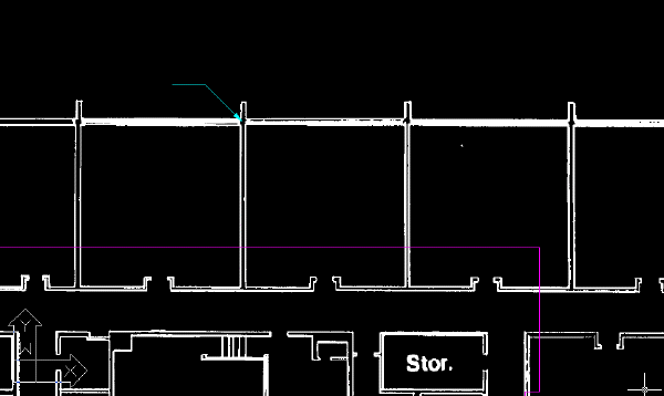
- When prompted, enter 34 feet (10.4 meters) for the source distance, and 25 feet (7.6 meters) for the destination distance.
- Use the
DISTANCE command to verify the width of the center classroom is now approximately 25 feet (7.6 meters).
Match the image to the vector linework
- Click
View menu Named Views. Then set the current view to
TU_extents.
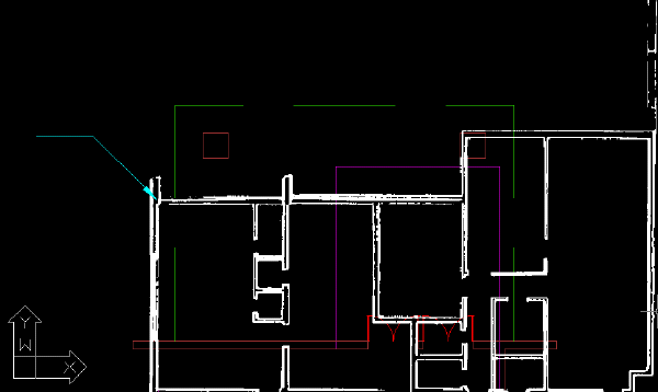
- Click
Raster menu CorrelateMatch. Then select the intersection of the outside walls at the upper-left corner of the building for the first source point.
Tip: Use Pan and Zoom to more clearly display this area of the drawing.
- Use an Endpoint
OSNAP to select the first destination point at the upper-left corner of the purple vector linework of the building.
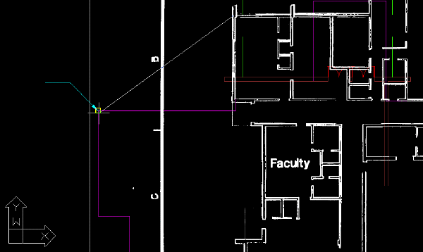
- For the second source point, select the intersection of the outside walls at the upper-right corner of the building.
- For the second destination point, select the upper-right corner of the purple vector linework of the building.
The image is aligned with the vector linework.
- Close the drawing without saving changes.