What's New: 2019, 2019.1, 2019.2
Start in the assembly environment with an assembly model open.
Miter
Miter the ends of two frame members.
-
 On the ribbon, click
Design tab
On the ribbon, click
Design tab  Frame panel
Miter .
Frame panel
Miter .
- Do one of the following:
 Click to select a single pair of frame members to miter.
 Click to select multiple frame members to miter.
-
 If single pair is enabled, click to select the first frame member to be miter cut. If multiple is enabled, select all frame members to be miter cut.
-
 If single pair is enabled, click to select the second frame member to be miter cut.
- To replace an existing end treatment with the miter, select the check box for Delete existing end treatments. Clear the check box if it is not necessary to delete an existing end treatment.
- Select or enter a distance between the mitered cuts.
- Click one of the miter types:
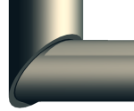
 Miter cut symmetrically to miter both selected frame members at the same angle.
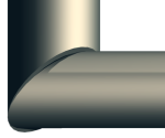
 Miter cut at one side to miter one frame member only.
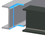
- For a miter between two frame members of different sizes, you can specify a simple angle cut at their intersection. Select the check box for Bi-sect Miter. The edges of the frame members do not meet.
- Bi-sect Miter selected
-
- Bi-sect Miter cleared (default)
-
- Click Apply.
- Continue to apply miters to frame members as needed. When you finish, click OK.
Trim and extend two frame members at their ends.
-
 On the ribbon, click
Design tab
Frame panel
Trim To Frame.
On the ribbon, click
Design tab
Frame panel
Trim To Frame.
-
Click to select the first frame member to trim or extend.
-
Click to select the second frame member to trim or extend. To include a published notch profile, click Apply notch profile.
To include a published notch profile, click Apply notch profile.
- If you intend to replace an existing end treatment with the cut, select the check box for Delete existing end treatments. Clear the check box if it is not necessary to delete an existing end treatment.
-
 Select or enter a vertical offset distance.
-
 Select or enter a horizontal offset distance.
- Click Apply.
- Continue to trim or extend frame members as needed. When you finish, click OK.
Trim/Extend To Face
Trim a frame member with a model face, or extend a frame member to a model face.
-
 On the ribbon, click
Design tab
Frame panel
Trim/Extend .
On the ribbon, click
Design tab
Frame panel
Trim/Extend .
-
Click to select a frame member to cut or lengthen.
-
Click to select a model face to use for the cut or extend.
- To replace an existing end treatment with the cut, select the check box for Delete existing end treatments. Clear the check box if it is not necessary to delete an existing end treatment.
- Select or enter the offset distance between the frame member and model face.
- Click Apply to extend or trim the frame member to the model face you selected.
- Continue to trim or extend frame members as needed, and then click OK.
The values generated by applying the Trim/Extend command to cut angles display in the iProperties/Custom tab as CUTDETAIL1, CUTDETAIL2, etc. and can be included in the Bill of Materials and Parts List.
Update panel Rebuild All.
Notch
Trim and extend two frame members at their ends.
-
 On the ribbon, click
Design tab
Frame panel
Notch .
On the ribbon, click
Design tab
Frame panel
Notch .
- Do one of the following:
- Click to select a single pair of frame members to notch.
- Click to select multiple frame members to notch.
-
Click to select the frame member to receive the notch.
-
Click to select the frame member that represents the shape of the notch.
- If you intend to replace an existing end treatment with the cut, select the check box for Delete existing end treatments. The end treatment is deleted before the command runs.
Clear the check box if it is not necessary to delete an existing end treatment.
- Click Apply to notch the selected frame members together.
- Continue to notch frame members as needed. When you finish, click OK.
Lengthen/Shorten Frame Member
Extend or retract one or both frame member ends.
-
 On the ribbon, click
Design tab
Frame panel
Lengthen/Shorten .
On the ribbon, click
Design tab
Frame panel
Lengthen/Shorten .
-
Click to select the frame member to extend or retract. Place the pick point near the end of the frame member to extend or retract.
- To replace an existing end treatment with the cut, select the check box for Delete existing end treatments. Clear the check box if it is not necessary to delete an existing end treatment.
- Click a choice to define the placement of the extension or retraction:
 Lengthen-Shorten Frame Member at one end
 Lengthen-Shorten Frame Member at both ends.
- Select or enter a value for the offset between the frame member and the model face. A positive number extends, and a negative number retracts.
- Click Apply to extend or retract the frame member you selected.
- Continue to extend or retract members as needed. When you finish, click OK.
Remove End Treatments
Remove end treatments, returning the selected frame member to its original state of creation.
-
 On the ribbon, click the Design tab. Click the Frame panel drop-down arrow and select
Remove End Treatments.
On the ribbon, click the Design tab. Click the Frame panel drop-down arrow and select
Remove End Treatments.
-
Click to select the frame member from which to remove the end treatments.
- Click Apply to remove the end treatments from the selected frame member.
- Continue to remove end treatments as needed. When you finish, click OK.