The intermediate fiber orientation tensor result shows the probability of fiber alignment in a specified direction evolves over time for the overmolded part.
Generate this result from an analysis that includes a Fill or Fill+Pack analysis for the following mesh types:
 Midplane
 Dual Domain
 3D
3D
- A fiber filled material is selected for the overmolded part.
- The Fiber orientation analysis if fiber material option on the Process Settings Wizard - Fill Settings dialog is enabled.
- The Output intermediate fiber orientation results option on the Fiber Solver Parameters dialog is enabled.
Understanding the result
The Intermediate fiber orientation tensor (overmolding) result shows how the probability of fiber alignment in a specified direction evolves of time for the overmolded part.
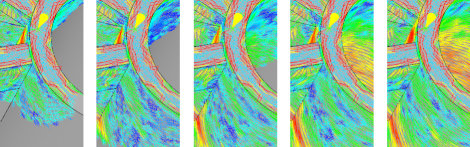
Fig 1: Intermediate fiber orientation tensor over time
Figure 1 shows the increase and then decrease of blue (low probability) tensors which illustrates how the fiber orientation tensor result changes through the injection cycle.
Midplane and Dual Domain analyses can also show the fiber orientation tensor at different positions through the thickness of the part at intermediate times if the profiled results output has also been enabled. A 3D analysis can only be displayed on the surface or cutting plane.
Fig 2: Intermediate fiber orientation through thickness
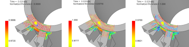
Figure 2 shows, from left to right, the fiber orientation tensor from the middle of the part to the surface for a Dual Domain analysis.
There are two ways to view this result. These are:
- Principal direction
- The direction in which most fibers align is the called the first principal direction. A value close to 1 indicates a high probability that the fiber alignment is in this direction. The first principal direction may be close to, but may not necessarily coincide with, the material flow direction.
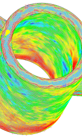
Fig 3: Intermediate fiber orientation result in the principal direction
The second and third principal directions are based on, and are at right angles to, the first principal direction. Their values also indicate the probability of fiber alignment in their respective direction.
As this is a probability result, the sum of the probability for all three principal directions equals 1.
- Tensor components
-
Fiber alignment in relation to a Cartesian Co-ordinate system can be displayed by selecting tensor components. This can be thought of as a 3x3 matrix. The Cartesian Co-ordinate system may be the Global Co-ordinate system or a Local Co-ordinate system defined by the user. The value of the matrix diagonal will always up to 1. The off-diagonal values represent the amount the alignments vary from the co-ordinate axes.
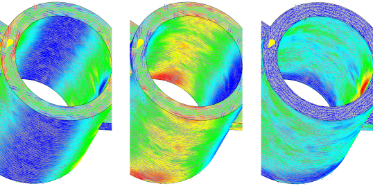
Fig 4 : Intermediate fiber orientation result in the Txx, Tyy, and Tzz orientation for the Global Co-ordinate system
Investigate the fiber orientation tensor through both time and part thickness for the overmolded part. Select
 (), select
Single dataset from
the Animate result over drop down list. By varying the
Time and
Normalized thickness values, fiber orientation through both time and part thickness can be understood.
(), select
Single dataset from
the Animate result over drop down list. By varying the
Time and
Normalized thickness values, fiber orientation through both time and part thickness can be understood.
This result only animates the change in the fiber orientation tensor through the injection cycle on the surface or cutting plane.
- Change the injection location to change the fiber orientation in critical areas
- Introduce flow leaders and deflectors to direct the flow
- Alter the thickness and location of walls, if possible, to enable a more gradual change in flow direction