An *.iges model is a representation of the model surface that needs to be converted into a volume prior to analysis.
There are three main parameters to consider when working with *.iges models.
Global edge length
An appropriate global edge length needs to be set when meshing an *.iges model. Use the Preview feature on the Generate mesh dialog () to view the proposed mesh density and adjust as required.
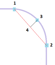
Chord height
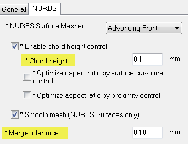
The chord height is used when calculating the edge length around a curve for an *.iges format. The edge length is shown by the distance 1 - 2, while chord height is represented by the distance 3 - 4 the cord length. By default the maximum chord height is 0.1mm.
- Small curves, as there are not enough elements to work with. The chord height must then be locally reduced.
Note: Fillets and other small features usually do not need to have fine mesh refinement.
- Very large curves, as a large number of elements might be generated. The chord height should then be increased locally .
Merge tolerance
By default the merge tolerance is 0.1mm. This parameter allows the software to create surfaces by merge face edges separated by less than the specified value. The *.iges format only provides a set of individual surfaces that are not connected. The merging of the faces forms a watertight body that is required for analysis.
 (). Select the
NURBS tab and enter the appropriate value.
(). Select the
NURBS tab and enter the appropriate value.