Coolant outlets need to be specified for specific cooling situations.
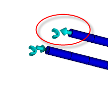
Often the CAD drawings supplied for analysis are also used for the machining of the mold. In these cases, cooling channels are represented as holes that can pass all the way through the mold and intersect with other channels.
- If a cooling circuit, comprised of beam elements, is a single path that does not intersect with another channel, there is no need to specify an outlet.
- Conformal cooling analyses
- Some imported CAD cooling channel models
Conformal cooling analyses
Some imported CAD cooling channel models
CAD drawings supplied for analysis are often used for the machining of the mold. In these cases, cooling channels are represented as holes that can pass all the way through the mold and intersect with other holes forming the cooling channel.
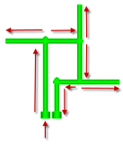
With only the coolant inlet specified, several flow paths are possible.
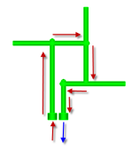
Add an outlet and the flow path is fully defined.
When the mold is manufactured, the end of the construction holes are plugged forcing the coolant to flow around the channel. Stagnant coolant accumulates in these dead ends.
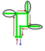
Retain these areas in the analysis, as the stagnant coolant heats up and contributes to the heat of the system. This is incorporated into the analysis.
To set a coolant outlet
- Click
 ()
()
- Click the outlet face of the cooling circuit, and the outlet is set.