Create support structures in Netfabb and test their performance in Simulation Utility.
Video length (8:49).
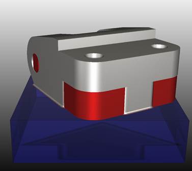
Support structures are used to mitigate excessive distortion during powder bed processing. However, these structures are themselves subject to the same forces that distort the part. In this tutorial, a geometry with a large overhang area is modeled using homogenous support structures, with options enabled to check for support structure failure.
We will use Netfabb to create support structures for this part. Follow the step-by-step instructions shown in the video. Sample files for use with the tutorials are available on the Download Page.
- In Netfabb, click .
- If it's not already there, add
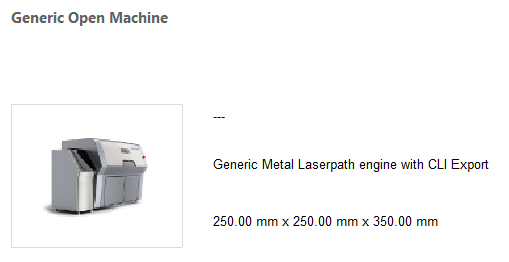
Generic Open Machine to your list of machines.
- In the My Machines dialog, click the Add Machine button.
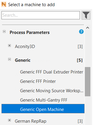
- In the
Select a machine to add dialog, scroll down the
Process Parameters list, expand the
Generic category, and click
Generic Open Machine.
- Click the Add to My Machines button at the bottom of the dialog.
- In the
My Machines dialog, with the machine selected, click
Open.
You should see Generic Open Machine selected at the top of the project model tree.
- Click and add the sample file Example_10.stl .
- In the left pane, make sure that Force above platform is not checked.
- To check the part position in relation to the platform, at the top of the window click
Move Parts
 and in the left panel, you see the X, Y, and Z values of the part's position.
It is important for this exercise to place the part directly on the platform, not above it. In the example below, the part's position has a Z value of 1.70 mm, so we must bring this to 0.
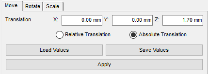
- Use the Translation Z field to move the part. Select Absolute Translation and set the Z value to 0.00 mm, then click the Apply button, and the Close button at the bottom of the panel.
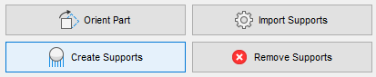
- Click
Create Supports.
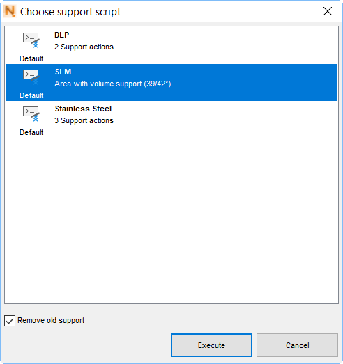
- At the bottom of the window, click
Run Support Script, in the
Choose support script dialog select
SLM, and click
Execute.
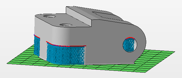
The lattice-like supports are created.
- Click Apply support.
- Click Start build simulation; in the dialog that opens, enter a suitable file path and name, such as Example 10, leaving in place the file extension .3mf. Click Save.
- In the
Start build simulation dialog, ensure that
Combine support volumes for simulation is checked, select the
Simulation Utility version, if both are available, and click
Simulate.
The exported file takes a minute or so to generate, then opens inside the Simulation Utility window.
- In the
Simulation Utility Browser, right-click on the support structure, which has a name that includes
_hulledsupport_, and select
Edit Geometry.
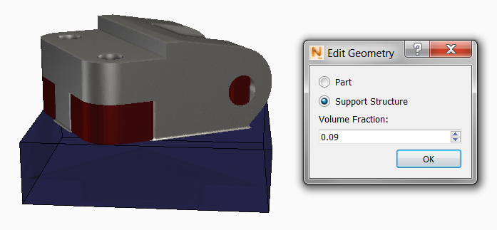
One benefit of using Netfabb to generate supports appears here, in that the Volume Fraction is automatically calculated during support creation. Volume fraction is the amount of the support volume that is occupied by physical structures rather than empty space. Leave the existing value unchanged.
- On the
Home tab, click
Machine to start setting up the simulation.
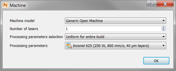
- In the Machine dialog, set Machine Model to Generic Open Machine and Processing Parameters to Inconel 625.
- Click OK to close the Machine dialog, and click , then click Snap to X and Y.
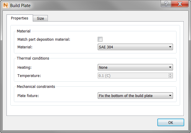
- In the Build Plate dialog, click the
Properties tab; here deselect
Match part deposition material and set
Material to
SAE 304.
- Click
OK, then click
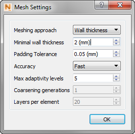
Mesh Settings. Set the
Meshing approach to
Wall thickness, and
Minimal wall thickness to
2 mm.
- Click
OK, then click
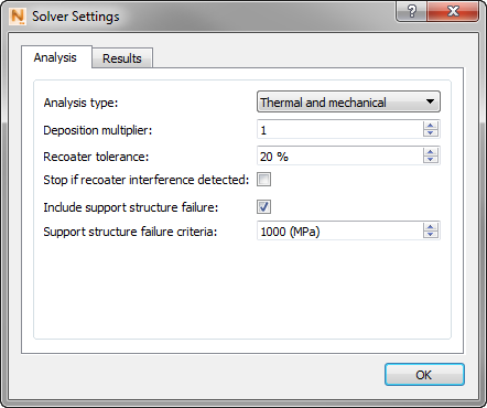
Solver Settings. On the
Analysis tab, select
Include support structure failure, and set the failure criteria to
1000 MPa.
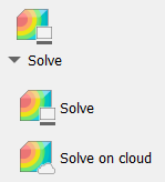
- Click
Solve to start the simulation, and save the project with a descriptive name.
When the simulation finishes, the results appear.
- Click
 to read the solver output.
- In the
Log Files window, click the
Mechanical tab, and scroll down, looking for Warnings.
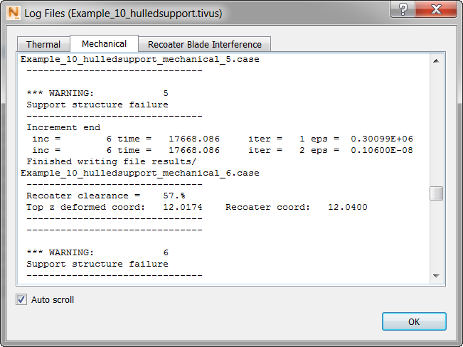
You may see several warnings of support structure failure. These indicate that the support structure failure criteria, specified in MPa units in the Solver Settings, was exceeded during simulation.
- In the Browser
Results folder, use the light bulb icons to show the
Structure Type results. In the
Animation panel, move the increment slider to the right to view the last increment before build plate removal.
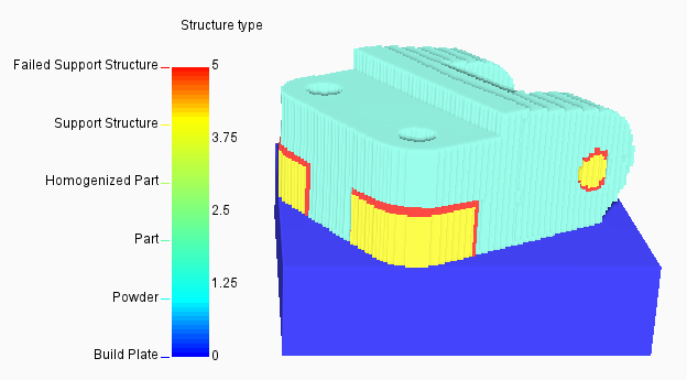
The Structure type results are color coded into 6 different element types, and the failed support structures are clearly visible in red.
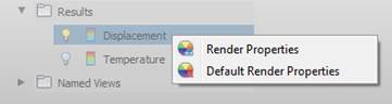
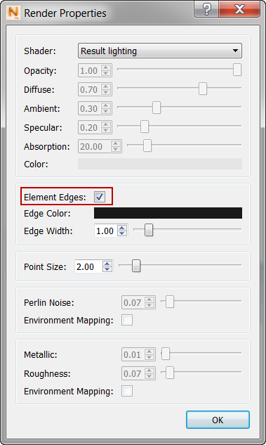
- If you want to turn off the element edges display for a clearer view, as shown above, right-click in the Results Browser, select
Render Properties, and deselect
Element Edges.
- Use the light bulb icons to show the Displacement results.
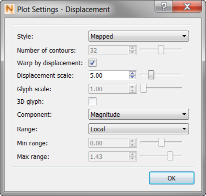
- Click
Plot Settings
 .
.
- Select
Warp by Displacement, and change the
Displacement Scale to
5.0 to exaggerate the displacement five times. Click
OK to exit the settings dialog.
For this example you may want to turn the element edges back on in the Render Properties dialog. The warped displacement results with visible element edges should look similar to the figure below:
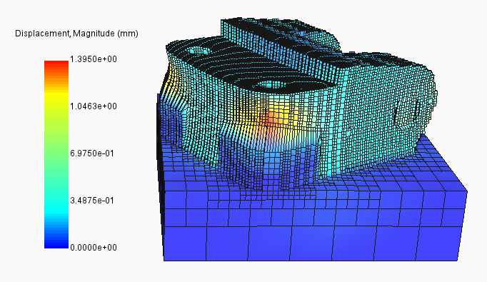
Note that the elements at the support-part interface look distended. Rotate the part and zoom into the distended region.
Observe the excessive displacement of the part at this location. You may want to go back to the Mechanical log file and make note of one or more specific time increments when the warnings of support structure failure occurred. You can enter those times into the Time field on the Animation panel of the Results tab to see the state of the build at each time.