Bar supports connect two points, one on the part, and the other one either somewhere else on the same or a different part or on the platform. As such, bars only support single points. Bars may be created as volume-less single-path entities or solid voluminous ones. Bars may also be connected into bouquets that merge multiple bars into tree-like structures which terminate in single trunks at their bottom end.
| Bar contour | Notes | |
|---|---|---|
|
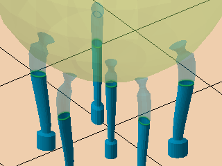
Bar contour |
The type of structure. 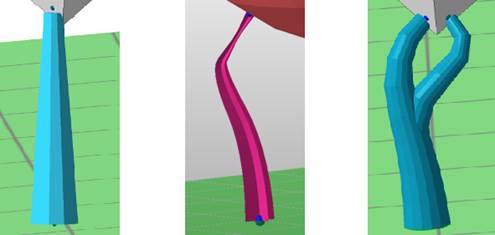 From left: Straight bar with a solid contour; curved bar with right angle on the part, a cross-shaped cross section, and a breaking point; curved and solid bar with bouquet structure. |
Cross, Solid Bar, Solid Cross |
|
Polygon corner |
Determines the number of corners for the solid bar. The more corners, the more rounded the bar's cross section becomes. |
|
|
Angle at top |
When set beyond 0, a pointy end is added to the normally blunt end that terminates evenly in the part surface.
Note: This point will intrude into the part mesh, so you may want to also work with
Distance to part to reduce or avoid unwanted duplication of toolpath at the intersection.
|
0-60 ° |
|
Crosswidth |
Determines the thickness of the contours for the solid cross. |
0.01-20.00 mm |
|
Radial type |
Used to create solid bars with oval cross-sections. It aligns the oval cross section by the semi-major axis with the X or Y axis, or radially away from the supported object's outbox's center:
|
|
|
Radial factor |
Used to create solid bars with oval cross-sections. Makes the semi-major axis as long as the semi-minor axis times this factor. |
|
|
Distance to part |
Defines the distance between part and support. A negative value will make supports intrude into the part mesh. |
|
|
Width on part |
Determines the contour width for bar ends that terminate on a part surface. |
|
|
|
Determines the contour width for bar ends that terminate on a part surface at their lower end. |
This is optional. To disable defining a separate width for the lower end of a bar, set this to -1. |
|
Width on platform |
Determines the contour width for bar ends that terminate on the build platform surface. |
|
| Breaking point |
Generates a section where the bar narrows and expands to create a defined breaking point near the part surface, making it easier to remove supports from the part later on. |
Notes |
|
Breaking point |
Toggle yes or no to activate the breaking point. |
|
|
Breaking point width |
Defines the strength of the bar at the breaking point. It will be easier to remove the bar with a thinner breaking point. |
|
|
Width on end |
Making the part wider at the end of the breaking point can increase adhesion of the bar to the part. |
|
|
Breaking point height |
Determines the distance between the anchor point on the part and the kink on the breaking point. |
|
|
Height on start |
Determines the length over which the breaking point reduces to its center. |
|
|
Height on end |
Determines the length over which the breaking point expands back to the original width, or the width of the end on the part. |
|
|
Right angle on part |
Determines whether bars should make a small curve to terminate in a right angle at the supported surface, rather than terminating at whatever angle they would otherwise have. |
|
|
Distance to right angle |
Determines the distance away from the supported surface after which the bar starts to curve towards the other end. |
|
|
Smoothing distance |
Determines the length of sections that form the curve. The shorter the section, the finer the curve is resolved, resulting in a smoother transition but also increased triangle count. |
|
| Pad on platform |
A pad is a widened cross section at the platform end of a bar support to reinforce adhesion to the platform surface |
Notes |
|
Pad on platform |
Toggles pad creation. |
|
|
Pad width |
Determines the width of the created pad. |
|
|
Pad height |
Determines the height of the created pad. |
|
|
Use density map |
Applies information provided by a 3D heatmap to lighten or strengthen structures locally. |