Manage project contents and operations
The project tree lists all parts, slices, machine workspaces, and other elements contained in the project. The relationship between these different entries is displayed in a hierarchical fashion in the project tree. For example, a module may be loaded on a part, and the loaded module is represented as a branch under the part. The entries in the project tree can be sorted into groups if necessary.
The project tree provides a number of details about the parts, slices, and structures in the model. For example, for parts these include level of detail, visibility, display color, need of repair, shell count, part number. This varies with the entry type. For example, slices have no shell count and cannot have their level of detail adjusted.
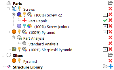
Example of parts, slices, and module branches loaded in the project tree.
- The first part, labeled
Screw_c2, shows an
 yellow lightbulb icon which indicates the part is visible. The
 warning sign on the
 display color swatch for
Screw_c2 indicates that it is damaged. You can also see that a
display color swatch for
Screw_c2 indicates that it is damaged. You can also see that a
 Part Repair operation has been opened for this part, and the
 green tickmark provides a shortcut to apply any repair actions taken during the repair operation.
- The second part, labeled
Screw (color), shows a
 bluish lightbulb icon which indicates the part is hidden while the
 colorwheel with a yellow lightbulb icon indicates that its actual color is currently active instead of its display color.
- Screw_c2 and Screw (color) are members of the group Screws.
- The
Sierpinski Pyramid shows up as a part containing
 multiple shells and also as having
 no actual color or texture.
- A
 slice stack of the
Pyramid has been created, and orange is its display color.
slice stack of the
Pyramid has been created, and orange is its display color.
- Other icons,
 Remove,
 Add, and
Apply Part Repair, provide additional functionality.
Add, and
Apply Part Repair, provide additional functionality.