Polyline supports are akin to fences. They support a part along a line that are formed by connecting anchors which are set either manually or generated automatically by cluster detection. Polyline supports may come in three main variants, a thin but otherwise featureless wall, the same again, but with holes to resemble a wire-fence-like structure, and a massive wall with a defined thickness beyond that one of a single toolpass.
|
Polyline type |
Sets the type of polyline. 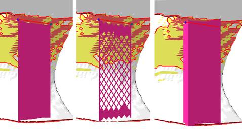 From left: Thin line, structure, massive polyline |
|
|
Distance to part |
Sets the distance between part and support. A negative value causes the support to reach into the part body. |
|
|
Smoothing distance |
Determines how many steps will be used to smoothen a polyline. The smaller the distance, the stronger the smoothing and the more triangles will be used. |
|
|
Smooth curves |
Switches the drawing of the resulting polyline supports through the placed anchors between discretely angled and continuously curved. |
|
|
Line width |
Specifies the thickness of a solid wall. |
Massive wall only |
|
|
Applies a radius to the ends of solid walls with thickness instead of leaving them square. |
Massive wall only |
|
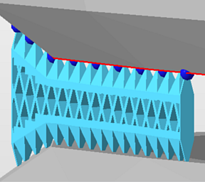
Structure properties |
Contains properties of the wall, see details below. |
|
|
Fragments |
Fragmentation creates gaps in normally continuous polyline support. Gaps make support easier to break off. See details below. |
|
|
Connection |
This group defines the connection between support, part, and platform ground. It is divided into multiple sub-groups. See details below. | |
|
Angled Block Support |
Set to Yes, this option enables a control element with which the support can be angled away from the default vertical. Switching from Yes to No and back to Yes remembers the support angling set previously. |

| Structure properties | ||
|---|---|---|
|
Structure pattern |
Determines the type of the support structure |
|
|
Width and Height |
Set width and height of the polyline |
|
|
Interval width and height |
Determines the distance between two structure units |
|
|
|
Values beyond 0 turn single-pass polylines without thickness into full meshes with volume. |
|
|
|
If the structure is set to become thickened, a value can be set to specify the thickness of the top connections separately, allowing to create conical transitions between structure and part. |
|
|
|
If the structure is set to become thickened, a value can be set to specify the thickness of the bottom connections separately, allowing to create conical transitions between structure and part. |
|
|
Stitch tolerance |
Set a tolerance in millimeters up to which a gap between the structures is not going to be stitched. A value of 0.01 mm is recommended to keep as default. |
|
|
Maximum height |
Polyline support will be at most this long. |
|
|
Fin |
Draws a single configurable fin from the middle of a polyline (or a polyline fragment, see Fragments section) off to the side, strengthening the polyline support with a backbone. See Fins section. |
Does nothing for closed polylines (eg. created by Cluster-contour with polyline). |
|
Use density map |
Applies information provided by a 3D heatmap to lighten or strengthen structures locally. |
|
|
Reverse thickening direction |
Inverts the drawing direction. For example, fins will be attached to the other side when this setting is flipped. |
|
| Fin | ||
|
Create fin |
Toggle fin creation. |
Yes, No |
|
Width |
The fin will be this wide.
Note: If any fragment shrinkage is specified, the width is scaled accordingly.
|
|
|
Keep distance to support |
Detach the fin from the support by this distance. |
|
|
Top distance to part |
The fin will end this distance short of terminating at the actual support's top end. |
|
|
Bottom distance to part |
The fin will end this distance short of terminating at the actual support's bottom end. |
| Fragments | ||
|---|---|---|
|
Fragment contour |
Toggle contour fragmentation. |
|
|
Fragment contour length |
The polyline will be fragmented into segments this long. |
|
|
Fragment contour gap |
Polyline fragments will be this far apart from each other. |
|
|
Shrinkage width |
The bottom borders of fragments will be at most this long. Can be used to create W-shaped fragments. |
|
| Connection | |||
|---|---|---|---|
| Top part | Refers to supports terminating in part surface at its top end. | ||
| Bottom part | Refers to supports terminating in part surface at its bottom end. | ||
| Platform | Refers to supports terminating in the platform surface at its bottom end. | ||
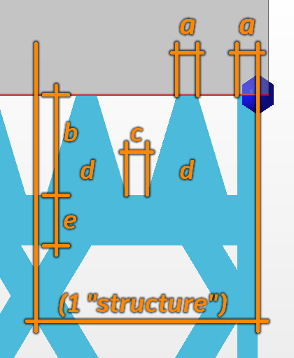
| Connection property | |||
|
Connection |
Type of connection |
Select from: Strip, Trapoid, Breaking Points, Triangles.
|
|
|
Connection width |
a |
 Connection properties |
|
|
Connection height |
b |
|
|
|
Pin distance |
c |
|
|
|
Pins per structure |
d |
|
|
|
Distance connection to structure |
e |
|
|
| Platform connection | This section defines the connection between support and platform ground. | ||
|
Connection |
Type of connection. See above for reference. | ||
|
Hatches |
Replicates the lower section of connections in parallel, up to 15 copies in each direction. This creates tapered, pedestal-like reinforcements. Accepts odd numbers up to 31 only, ignores even numbers. | ||
|
Hatch distance |
Distance between replications | ||
| Triangles on platform | Adds reinforcing triangle-shaped struts to the platform connection, perpendicular to the polyline or contour. Not available when Angled Block Support is active. | ||
|
Distance |
The interval between struts | ||
|
Width |
The width at the base of the struts. The struts are always equilateral triangles, so changing the width modifies the height accordingly. | ||