Volume supports are hollow, regular structures similar to pipes with a square cross section. To create volume supports, you must define at least three anchor points to form an area that can have volume supports applied. Line types, structure properties, fragments and connection types can be adjusted.
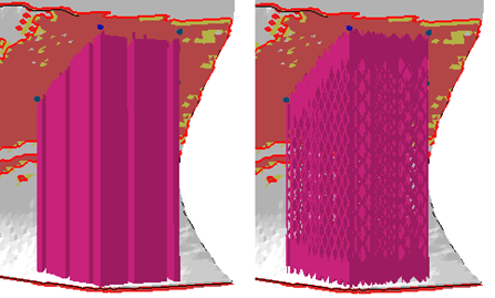
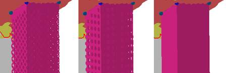
Left: Solid volume supports divided into fragments. Right: Volume supports built from a patterned structure.
|
Filling Type |
Switch the support walls between Hollow (solid) and Structured.
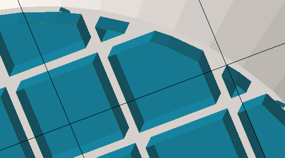 Applied default hollow supports. A cut via clip plane demonstrates the cluster's contour, the fragments' cross section, the terminating surface at the top, and the stand-off against the part surface. 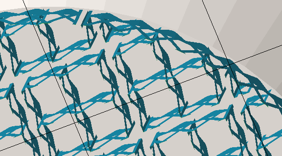 Applied default Structured supports. Note the gap in the circumference. |
|
Top distance to part |
A stand-off distance between part and supports. |
|
Bottom distance to part |
A stand-off distance between part and platform. |
|
Structure Properties |
Contains properties of the wall, see details below. |
|
Raster |
Settings for filling structures. See details below. |
|
Contour |
Settings for the outer contour of the support structure. See details below. |
|
Connection |
This group defines the connection between support, part, and platform ground. It is divided into multiple sub-groups. See details below. |
|
Fragments |
Fragmentation creates gaps in normally continuous polyline support. Gaps make support easier to break off. See details below. |
|
Angled Block Support |
Set to Yes, this option enables a control element with which the supports can be angled away from the default vertical. Switching from Yes to No and back to Yes remembers the support angling set previously. |
| Structure Properties |
Note: This section is available only when
Filling type is set to
Structured.
|
|
|---|---|---|
|
Structure pattern |
Switch between Wired wall (left), a Punched plate (middle), and Solid (right) to determine the wall pattern of volume supports.
|
|
|
Width and height |
Width and height of the hole shapes for Wired wall and Punched plate. |
|
|
Interval width and height |
Distance between neighboring holes to the sides and to those above and below. |
|
|
Thickening up Structure-Hatches |
Volume support walls are merely such that they result in single-line toolpasses. To make the structures thicker, as in, inflate them into hollow structures, this value can be used Notes
|
|
|
Thickening up top connections |
If the structure is set to become thickened, a value can be set to specify the thickness of the top connections separately, allowing to create conical transitions between structure and part. |
|
|
Thickening up bottom connections |
If the structure is set to become thickened, a value can be set to specify the thickness of the bottom connections separately, allowing to create conical transitions between structure and part. |
|
|
Stitch tolerance |
Set a tolerance in millimeters up to which a gap between the structures is not going to be stitched. A value of 0.01 mm is recommended to keep as default. |
|
|
Maximum height |
Produces support structures only up to this length. Supports will end in mid-air, if necessary. |
|
|
Solid structure for height |
Over this distance from the bottom end of the support, structured support will have no pattern, only continuous surface. |
Has no effect for types other than Wired Wall and Punched Plate. |
|
Fin |
Draws a single configurable fin from the middle of a polyline (or a polyline fragment, see Fragments section) off to the side, strengthening the polyline support with a backbone. See Fins section. |
Does nothing for closed polylines (eg. created by Cluster-contour with polyline). |
|
Use density map |
Applies information provided by a 3D heatmap to lighten or strengthen structures locally. |
|
| Fin | ||
|
Create fin |
Toggle fin creation. |
Yes, No |
|
Width |
The fin will be this wide.
Note: If any fragment shrinkage is specified, the width is scaled accordingly.
|
|
|
Keep distance to support |
Detach the fin from the support by this distance. |
|
|
Top distance to part |
The fin will end this distance short of terminating at the actual support's top end. |
|
|
Bottom distance to part |
The fin will end this distance short of terminating at the actual support's bottom end. |
| Raster | |
|---|---|
|
Rotate by Z |
Sets the general alignment of filling structures. Filling structures are aligned globally, as in, against the platform coordinates. |
|
Hatch distance |
Sets the distance between the inner structure units. The number of inner structure units and the density will be affected.
Note: Not available when
Hollow-type filling.
|
|
Filling strategy |
Defines in which directions the outer contours of the volume supports will be filled: In both X and Y direction, just in Y, or no filling at all. Notes
|
| Contour | Settings for the outer contour of the support structure. |
|---|---|
|
Contour count |
For values above 1, repeats the contour in concentric layers towards the inside. If no additional contour is requested, the volume-filling structures will terminate in the outer contour. |
|
Contour distance |
The gap between repeated layers. |
|
Smoothing distance |
Use this to adjust the mesh resolution of the contour to match the size of details of the supported skin. A very detailed skin, when sampled along its surface, may have details smaller than the sampling (effectively, the smoothing distance), so support connections may miss connecting with the surface in these spots. |
| Connection | This group defines the connection between supports, part, and platform ground. It is divided into multiple sub-groups. | ||
|---|---|---|---|
| Top part |
Refers to supports terminating in part surface at its top end. |
||
| Bottom part |
Refers to supports terminating in part surface at its bottom end. |
||
| Platform |
Refers to supports terminating in the platform surface at its bottom end. |
||
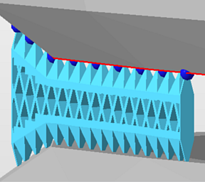
| Connection in Y | |||
| Connection by layer |
A way to create higher surface quality along the supported downskin is to connect the structured supports through a clone of the connection area, creating a contour-hugging layer along it. For the reference on this option, see the separate table further down. |
||
| Connection property | |||
|
Connection |
Type of connection |
Select from: Strip, Trapoid, Breaking Points, Triangles.
|
|
|
Connection width |
a |
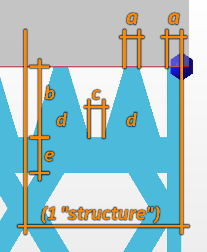 Connection properties |
|
|
Connection height |
b |
|
|
|
Pin distance |
c |
|
|
|
Pins per structure |
d |
|
|
|
Distance connection to structure |
e |
|
|
| Platform connection | This section defines the connection between supports and platform ground. | ||
|
Connection |
Type of connection. See above for reference. |
||
|
Hatches |
Replicates the lower section of connections in parallel, up to 15 copies in each direction. This creates tapered, pedestal-like reinforcements. Accepts odd numbers up to 31 only, ignores even numbers. |
||
|
Hatch distance |
Distance between replications |
||
| Triangles on platform | Adds reinforcing triangle-shaped struts to the platform connection, perpendicular to the polyline or contour. Not available when Angled Block Support is active. | ||
|
Distance |
The interval between struts |
||
|
Width |
The width at the base of the struts. The struts are always equilateral triangles, so changing the width modifies the height accordingly. |
||
| Connection by layer | |
|---|---|
|
Create layer |
Toggles whether to use this type of connection. |
|
Refine layer |
If it is not possible to create a copy of the layer surface, the supported structure will be recreated through triangulation of anchor points. The higher this value, the higher the accuracy of the triangulation. |
|
Top layer height |
Defines the thickness of the layer. |
|
Top layer distance to structure |
Sets the distance between the top layer and the structure. |
|
Pin type |
The actual connection between the part and the layer is usually done with pins. Set the type of pins here by choosing from Cross or Cube. Alternatively, disable the pins entirely and connect the layer fully to the part. |
|
Pin width |
Determines the width of a pin. |
|
Pin density |
Determines the density of the pin structure. The smaller the value, the more pins will be created. |
| Fragments | Fragmentation of volume supports into individual blocks makes it easier to break the supports from the part. |
|---|---|
|
Raster |
|
|
Fragments |
Turn fragmentation on or off. |
|
Fragment size X |
Fragment size in X direction. |
|
Fragment size Y |
Fragment size in Y direction. |
|
Fragment gap |
Describes the distance between two fragments. |
|
X shrinkage |
Shrinks the fragment at the bottom end of the x axis, to have a wider fragment at top, whose size decreases to the set value |
|
Y shrinkage |
Shrinks the fragment at the bottom end of the y axis, to have a wider fragment at top, whose size decreases to the set value |
|
Contour |
|
|
Fragment contour |
The cluster-enveloping contour can be fragmented as well, using this toggle. |
|
Fragment contour length |
Defines the length of a fragment unit. |
|
Fragment contour gap |
Defines the gap between two fragment units |