October 2018
ReadMe for Autodesk® Nastran® In-CAD 2019.2.
Autodesk, Inc.
Summary
In a continuing effort to provide high quality products, Autodesk has released Autodesk Nastran In-CAD 2019.2. This document highlights open issues with Autodesk Nastran In-CAD 2019.2 and provides information that is useful while using this software.
Installation Instructions
-
Before you begin
- Be sure that you computer hardware and operating system conform to the specifications found on the System Requirements page.
- The supported Autodesk Inventor versions (Standard and Professional) are 2019 and 2019.1.
- Close all Autodesk applications before you install, maintain, or uninstall Autodesk Nastran In-CAD 2019.1.
Notes
- Nastran In-CAD 2019.2 upgrade will uninstall Nastran In-CAD 2019 before installation. You need not uninstall Nastran In-CAD 2019 (Version 2019.0.0.103) before installing the Nastran In-CAD 2019.2 Upgrade.
- Nastran Editor and Nastran Command Solve now work with the Nastran In-CAD License (Standalone or Network). For using Nastran Editor or Command Solve, first activate the Nastran In-CAD License and then it will be activate for Nastran Editor and Command Solve as well.
-
To install Autodesk Nastran In-CAD 2019.2
- Download the executable file and unzip the files on your computer.
- Double-click Setup.exe to start the installation.
- In the Configure Installation page, set preferences.
- After configuration, start to install.
- When the installation is done, click Finish.
-
To activate Autodesk Nastran In-CAD 2019.2
- Start Autodesk Inventor.
- On the Tools menu > Add-ins, make sure the Autodesk Nastran In-CAD 2019 Add-in is checked (enabled) in the program's add-in manager.
- Open a new document to start the licensing and activation process. Click on
File
 New. The
Let's Get Started (LGS) window appears:
New. The
Let's Get Started (LGS) window appears:
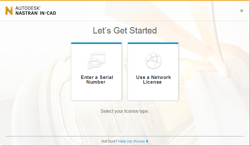
- Click Enter a Serial Number for a standalone license, or Use a Network License for a floating (network) license.
- If you have a network license, enter the port number and server name in the format
port@servername. It might be necessary to use the server IP address instead of the server name. Using an IP address can resolve Domain Name Service (DNS) name resolution problems.
Standalone licensing requires you to enter your Autodesk In-CAD Serial Number and Product Key.
- If you experience issues connecting to your server and obtaining a license, it might be necessary to add the System Environment Variable
FLEXLM_TIMEOUT, with the Variable Value set to 15000000. The timeout value is in microseconds, and this value represents a 1.5 second timeout interval. Over VPN connections and slow wide area networks, the default timeout (without the specified system variable) is often inadequate. If you still encounter difficulties, increase the timeout value further.
 Note: You can also set this variable as a User Environment Variable. The advantage of making it a System Variable is that it will be applied for any user that logs into the workstation. In a multi-user situation, you would have to define the User Variable in every user's profile.
 - Log in using your Autodesk User ID account. If you do not have an account, you can create one here:
https://accounts.autodesk.com/
Note: To configure the network license manager, refer to the topic: Installing the Network License Manager. To request a network license file, refer to the topic: Requesting a License File.
-
When creating a deployment image of Autodesk Nastran In-CAD 2019.2
- Refer to the steps given on the Preparing for Deployment web page.
- Enter your Autodesk Nastran In-CAD 2019.2 serial number when creating a deployment.
-
To verify the installation is successful
- Start Autodesk Inventor and open a CAD model.
- Switch to the Environments tab and click on the Autodesk Nastran In-CAD icon.
- Click the About button in the Nastran Support panel. If the About box displays Autodesk Nastran In-CAD Version 2019.2.0.NNN (N for any digit) and Autodesk Nastran 2019 Version: 13.2.0.NNN, the installation was successful.
Summary of Known Issues
User Interface
- The Undo and Redo functionality is currently blocked while working in the In-CAD environment.
- Visualization can be incorrect for rigid connectors when using the 'create point at center' option, but it works fine for large assemblies, sub-assemblies and parts.
- In the Include Group dialog, the 'New Group' button is not available.
CAD
- Only Structural Members created using Inventor Frame Generator are supported. Structural members created using "Pattern" functionality are not supported.
- Frame generator features like Lengthen/Shorten and Trim are not supported.
Meshing
- Weld beads are not supported for meshing.
- Mesh connectivity is not working for curve/arc meshing of line elements.
- Node and Element Label display have been disabled in In-CAD for Inventor due to a graphics performance issue. Display size and color for Node is currently not working.
- Zero length spring between two coincident points doesn't generate CBUSH.
- Unable to mesh copied Structural members.
Loads and Constraints
- A Moment Load only supports face selection as the entity where the moment is applied. You can select an edge or vertex as the entity in the Moment Load dialog, but there is no warning that this is not supported, even after you hit OK. The analysis will solve for both cases, but the load will not be considered in the solution.
- Using the thrust load type of Bearing Load is not supported.
- Dynamic display of load and constraint glyphs has been removed due to a performance issue. Click the Preview checkbox in the Loads and Constraints dialogs to update the glyphs in the canvas.
- Display of glyphs for loads and constraints on the deformed model and for animations is disabled.
- Unable to select edge for a geometric entity that is already selected for Load.
- CFD temperature interpolation is not currently supported for parabolic elements; linear elements are recommended.
Results
- The Contour icon in the Ribbon remains depressed when switching between models, and will not work correctly for some models. Workaround: Close and reopen the model, or run the analysis again for the active document.
- Beam diagram plots are not shown from the Mini Toolbar. Use the Plot dialog to see beam diagrams.
- Grid Point Forces results for 1D and 2D elements are not included in the solution output.
- While animating results, if you uncheck Loads from the Object visibility menu in the ribbon bar, the loads are still displayed.
- The Probe tool does not function properly when the Inventor View option is set to Perspective. Workaround: Use the Orthographic viewing mode.
Other
- In the Laminate dialog, the ABD matrix calculation is not working as expected.
- The Stress/Strain output option in the Laminate dialog is not defined properly when the Use Global Ply checkbox is selected.
- Deleting an Offset Surface from a duplicated analysis affects previously related shell properties in other, inactive analyses.
- Rigid Body connectors defined for models having regular shapes (for example, a triangle or torus) are not acting at the center of gravity of the selected entities.
Thank you
We thank all our customers who help us to identify and report issues. These reports will give us the opportunity to improve the product and provide you with the best solution in Autodesk Nastran In-CAD simulation. We also thank you for your continued business and for the feedback regarding the content of this release.