For this simulation, we’ll apply line elements to our structure. To do so, we’ll create a new line type idealization.
- Copy the following text:
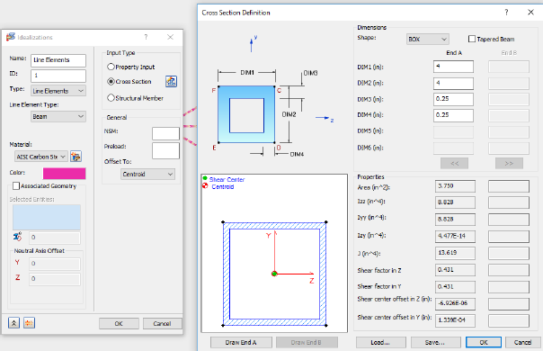
strCmdFornewIdealization = "<NewIdealization Name=""Line Elements"" ID=""1"" Type=""0"" LineElementType=""1"" InputType=""2"" ShapeType=""12"" HasTapperedBeam=""0"" DIM1_EndA=""0.1016[m]"" DIM2_EndA=""0.1016[m]"" DIM3_EndA=""0.00635[m]"" DIM4_EndA=""0.00635[m]"" HasAssociatedGeo=""0"" PreLoadType=""0"" OffsetType=""0"" AddToFEModel=""1"" Color=""11087083"" CoodinateSystemID=""0"" MaterialID=""1"" EntitiesCount=""0""/>"
Type = 0 denotes the use of line elements. LineElementType = 1 denotes the use of beam elements. InputType = 2 and ShapeType = 12 denote the use of box shaped cross-sections for the line elements.
These commands are equivalent to defining the idealization through the user interface.
- Paste the text below the existing commands in the Edit Rule dialog.
- Press the Enter or Return key twice to jump down to a new line.