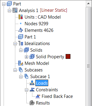
- Right-click on
Loads under
Subcase 1 and choose
New. In this subcase, the load is a 100 KN force applied to the first bolt hole of the bracket in the positive x-direction.
- Enter
Axial Loading
in the
Name field.
- Select the interior surface of the first bolt hole farthest from the back face and type in
100E3 for
Fx.
Note: In the
Display Options section of the Load dialog, you can adjust the size, number, and color of the load symbols that appear in the part display.
- Be sure that
Subcase 1 below the
Subcases list is selected.
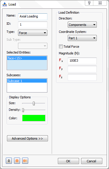
- Then click
OK.
 You can also drag-and-drop different entities in the tree view. For example, the
Axial Loading
load and the
Fixed Back Face
constraint can be dropped on top of the
Subcase 1 name.
You can also drag-and-drop different entities in the tree view. For example, the
Axial Loading
load and the
Fixed Back Face
constraint can be dropped on top of the
Subcase 1 name.
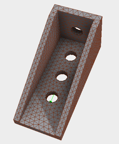
- The model should look as shown below.
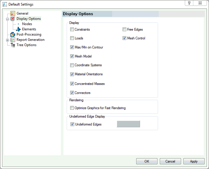
You can hide the loads and constraints.
Click on
Autodesk Nastran menu tab on the top of the CAD interface, and then choose
Default Settings under the
System panel on the ribbon. Then click
Display Options and uncheck the
Loads and
Constraints checkboxes. They can also be hidden by right-clicking on the
Loads or
Constraints within the
Subcases section in the tree and checking
Hide All.