Learn about the analytical elements used in a script, element priority, tolerance, and dataflow.
Model Elements
- Analytical framings - for structural beams and braces.
- Analytical columns - for structural columns.
- Analytical floors - for structural floors.
- Analytical walls - for structural walls.

The algorithm operates on both physical and analytical objects.
Other types of objects, such as windows and stairs, are filtered out of the selection right after launching the script. If you select physical elements only, the analytical elements are obtained directly from the selected physical objects.
All the elements that are out of the selection will not be considered by the script and will not be modified.
Selection mode allows you to pick all the objects included in the selection box drawn in the active view in Revit. All the objects - structural and non-structural - included in the selection range are automatically counted.
The algorithm checks which of the selected physical objects contain an analytical model. If the Enable analytical model parameter of an element is off, the element will be taken as a non-structural object and, together with other non-structural elements (e.g. railings, pipes, symbols), it will be filtered out after launching the script.
Element Priority
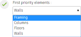
- Framing (beams and braces)
- Columns
- Floors (including foundation slabs)
- Walls
You can decide what type of element is the first priority element. The first priority elements act like master elements and slave elements snap to them.
The geometry of the first priority elements will be modified only if starting from the default analytical model or if you select adjusting elements within a category.
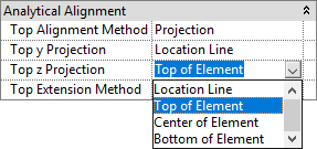
Start from Default Analytical Model
This option simulates the manual modification of analytical element placement in regard to their physical objects via their property sets and selecting: Center of Element.
-
Analytical beams are moved to the center lines of the physical beams, along their axis.
-
Analytical braces are moved to the center lines of physical braces, along their axis.
-
Analytical columns are moved to the center of physical columns, along their axis.
-
Boundaries of analytical floors are coherent with boundaries of their physical bodies; the analytical floors are levelled at the face in the middle of the physical floor's thickness.
-
Boundaries of analytical walls are coherent with boundaries of their physical bodies and are placed in the centerline of physical walls.
Tolerance
Tolerance is a measurement of proximity. If elements defined as master and slave are close enough, the slave elements are snapped to master elements. Otherwise, the slave elements are not snapped to the master elements.
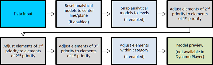
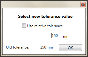
If the Force tolerance to change is set to True, when you use the Run script button, a dialog appears.

- Relative tolerance: calculated as the percentage of each element's bigger dimension in cross section or its thickness in case of floors and walls. This type of tolerance will be different for each of the elements.
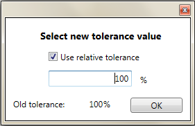
- Absolute tolerance: it is a single value for the entire project in the current project unit.
Snap Elements to Levels

This option does not consider user-input tolerance and simply draws element nodes to the nearest level.
Adjust Elements within Category

After adjusting between first, second and third priority elements, the script can adjust elements of the same type (category).
Objects of greater importance are called master elements and objects of lower importance are considered slaves. The slaves are adjusted to masters of the same category.
- For Framings:
- If framing elements are of different cross-section areas, the one with the higher value is chosen as the master element.
- If framing elements are of the same cross-section area, inclination is taken into account - more horizontal beams or braces are considered as masters.
- For Columns:
- If column elements are of different cross-section areas, the one with the higher value is chosen as the master element.
- If column elements are of the same cross-section area, inclination is taken into account - more vertical columns are considered as master for sloped columns.
- For Floors and Slabs:
- If floor elements are of different thicknesses, the one with the higher value is chosen as the master element.
- If floor elements are of the same thickness, due to lack of inclination, the floor ID number is taken into account.
Dataflow