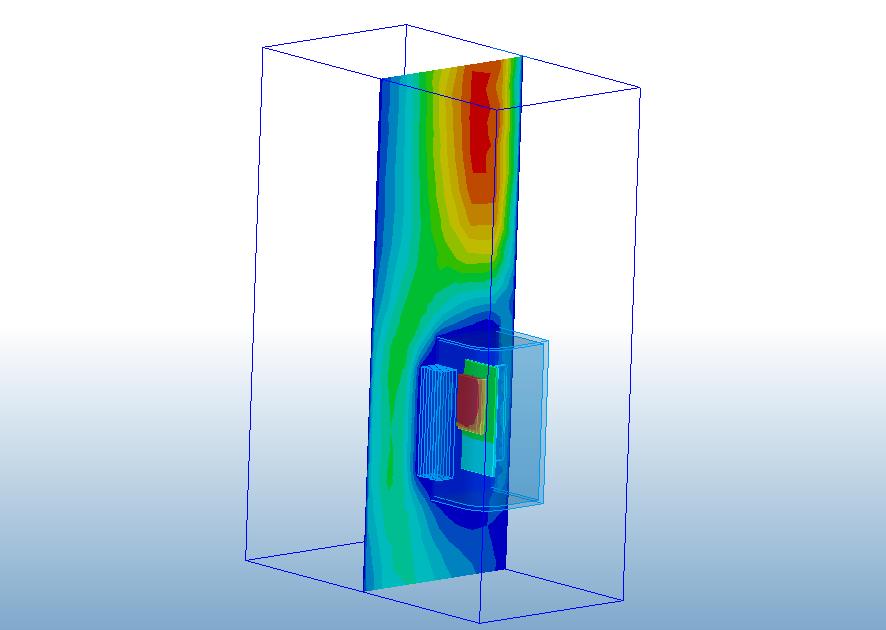
Many devices are immersed in a fluid (air or water, for example). A key factor in the design of such parts is how the fluid flows around the device. Examples include:
- Motorcycles and bicycles
- Aircraft
- Automobiles
- Electronic devices subject to external natural convection
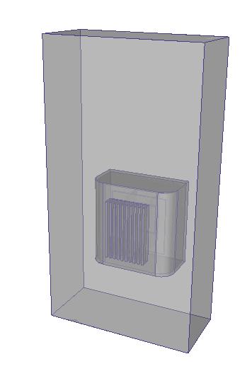
In all of these cases, the volume that surrounds the device is rarely included as part of the production CAD model. To analyze the flow, it is necessary to add a surrounding volume to the model.
With the External Volume tool, the surrounding air (or fluid) can be constructed directly on the simulation model within Autodesk® CFD, without having to add it to the CAD geometry.
![]()
To access External Volume Creation, click Setup (tab) > Setup Tasks (panel) > Geometry Tools, and click the Ext. Volume tab.
Alternatively, right click on the Geometry branch of the Design Study bar, and click Edit...
Using External Volume Creation
The External Volume tool creates a rectangular volume that completely surrounds the original geometry.
The surfaces and edges of the volume cannot contact or intersect any part of the model. The minimum size is 5% larger than the geometry in all three Cartesian directions.
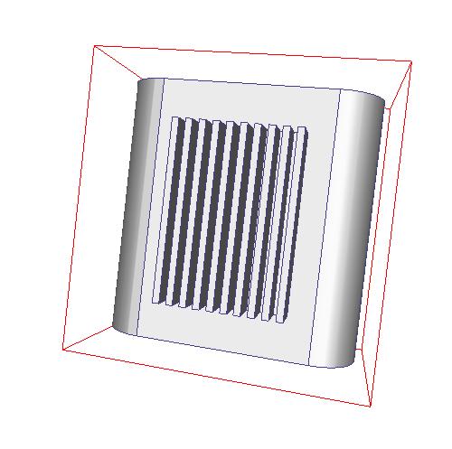
When the External Volume tab is first opened, a red outline of the external volume surrounds the model:
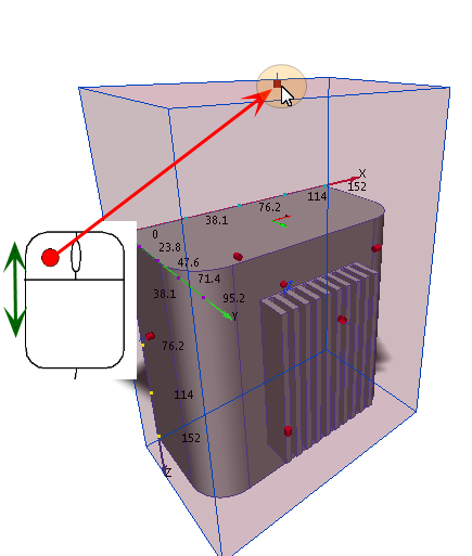
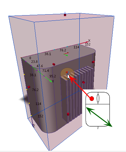
To resize an external volume:
- Click and hold the left mouse button on a grab handle.
- Drag with the mouse:
To move or rotate an external volume:
- Click and hold the axis or arc on the triad.
- Drag with the mouse:
When finished, click the Create button.
An external volume becomes part of the analysis, and can have boundary conditions, materials, etc., applied to it.
