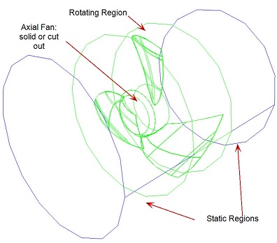
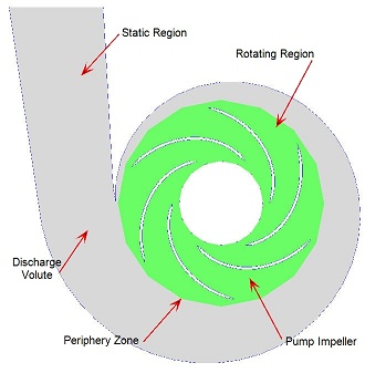
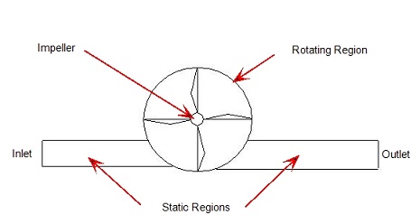
The Autodesk® CFD rotating machinery capability analyzes rotating devices using a locally rotating frame of reference. This region completely surrounds a rotating object, and is called the rotating region.
Areas in the model that are not rotating are analyzed in a static (absolute) frame of reference. These regions are called static regions. (Fluid in a static region can move, but the volume itself does not.)
The following are geometric considerations for setting up rotating analyses:
- Each rotating object must be completely immersed in a rotating region. Rotating regions rotate using their own relative rotating frame of reference.
- The mesh that is generated in a rotating region will physically rotate with the parts that are immersed.
- Immersed parts can be modeled as voids or as solid within the rotating region. Solid objects in a rotating region rotate at the same speed as the rotating region.
- The interface between a rotating and a static region is called the periphery zone. Within the periphery zone, the outer element faces of the rotating region slide along the neighboring element faces of the static region.
- The size and shape of a rotating region should correspond (loosely) to that of the rotating device. Rotating regions are usually fairly simple cylindrical shapes. This allows the element faces on both sides of the periphery zone to match.
- The rotating region should extend to roughly half-way between the outer blade tips and the closest point of the surrounding non-rotating wall.
- Do not apply any boundary conditions to the periphery zone. Care should be exercised when constructing fluid geometry so this is not necessary.
- Rotating regions must not overlap. Devices with interfering rotors such as gear pumps cannot be modeled with the rotating machinery capability because their rotating regions overlap. Instead, use angular motion.
- A rotating region cannot directly contact a non-rotating solid region, even if the solid is not inside of the rotating region. An example is a solid annulus surrounding the outside of rotating region. The result is that the solid annulus (which is supposed to be static) will rotate.
- Objects within a rotating region that have a uniform cross-section that satisfy the requirements for mesh extrusion can be extruded. The mesh inside of the rotating region, however, cannot be extruded.
The following graphics illustrate these principals:


- If the blade tip clearance is extremely small (as is the case when there are tight seals), the surrounding static region can be eliminated. An example is shown:

- A rotating region must not be in direct contact with a solid region. The outer edge of the rotating region must either be a fluid or an exterior boundary.