Geometry
Because the initial position of moving objects can be set in the Motion task dialog, objects can be constructed in the CAD model where it is convenient. When preparing the analysis model in Autodesk® CFD, the object can then be moved to its correct starting location. Note that all bounds information (for flow-driven analyses) will be relative to the selected starting position.
Moving objects can start completely inside the flow volume, partially inside, or completely outside. Moving objects can pass through the flow volume, and exit completely. If the moving solid starts outside of the flow volume but overlaps or even touches it, then the volume outside of the flow volume will be maintained as part of the flow volume, even after the solid leaves that region. This is illustrated:
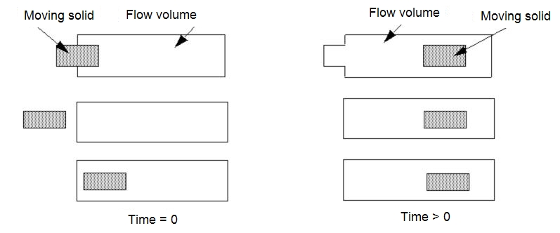
When an object moves through the fluid volume, the mesh of the object will appear to overlap the flow mesh. The solid elements will block out the fluid elements, and the fluid velocity is displayed as zero where the solid overlaps the fluid.
If heat transfer is of interest, then the energy equation is solved between the fluid and the solid nodes. Obviously the heat transfer between the moving solid and the fluid will be a function of the respective materials as well as the velocity of the solid and of the fluids.
The motion of a moving solid can be described such that the solid will collide with static solids. The solver will allow this type of motion, and care should be taken to ensure that physically real solid motion is defined. A Preview function is provided that allows the motion to be “practiced” prior to running the analysis. This is described in the Motion section.
Meshing
Autodesk® CFD uses a “masking” technique to model the interaction between moving solids and the fluid through which the solids move. As a moving solid passes through fluid, its elements mask the fluid nodes, meaning that the velocity on those nodes is governed by the motion of the solid. The mesh density of a moving solid and the fluid in its path must be fine enough to adequately represent the interaction between the solid and the fluid.
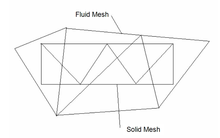
This image shows a fluid mesh that is much too coarse. As the solid moves through the fluid, there are times when the solid elements do not mask any fluid nodes. The result is that the solid has no effect on the fluid:
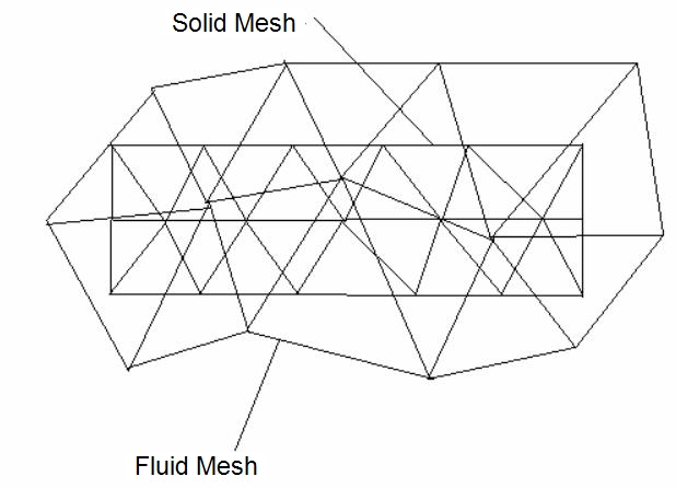
If the fluid mesh is refined so that there is one row of masked nodes within the solid, the mesh is still too coarse. Because of the motion of the solid, a pressure gradient will exist through it. With only one row of masked fluid nodes, only one pressure value can be transferred to the fluid at any given location. The gradient is lost:
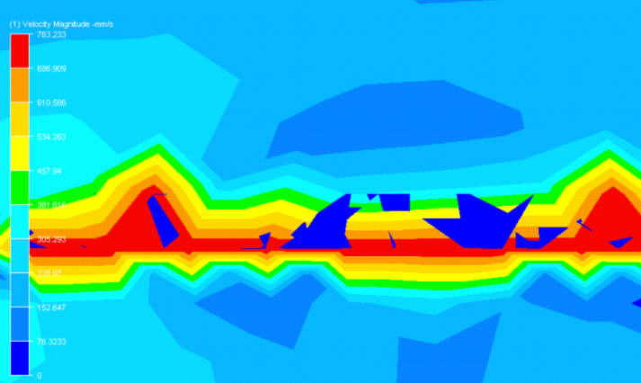
The velocity results are shown for this mesh. The velocity field along the solid object is very irregular, and should appear all blue. The red areas are the fluid results “bleeding through” because of an inadequate fluid mesh:
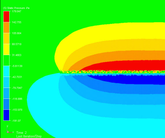
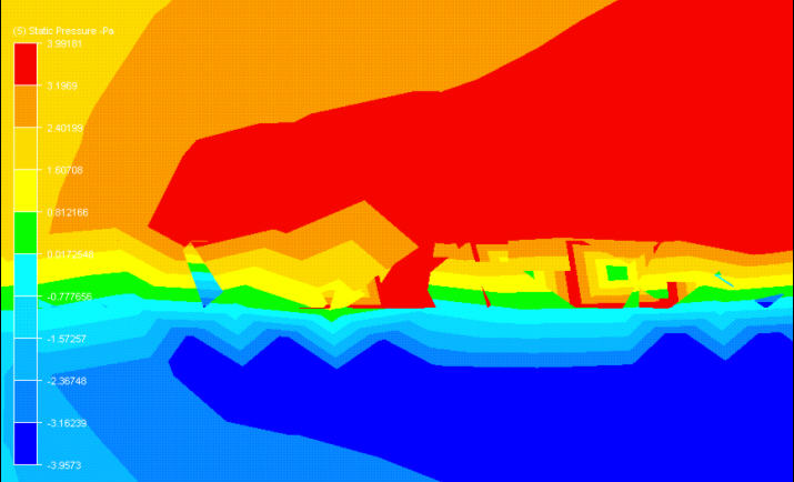
The pressure field with this mesh is highly irregular as well:
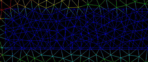
To adequately mesh the moving solid and fluid path in this example, a minimum of two rows of masked nodes throughout the fluid path are required.
A more universal guideline is that the moving solid must be meshed finely enough to resolve gradients through it, and the fluid path must be meshed with a similar element size.
Such a strategy will allow proper masking of fluid nodes, and will support gradients within the pressure field:
The velocity field for this finer mesh is shown. No “bleed-through” occurred, and the results appear quite plausible:
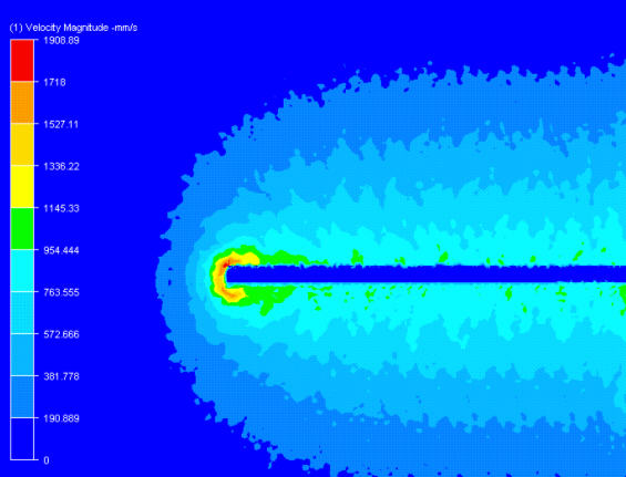
The multiple layers of masked nodes allow the pressure gradient to be resolved well, as shown on the right. As the object moves upward, high pressures on the top surface and lower pressure on the bottom surface are apparent:
