In many AEC applications, solar radiation striking external walls and passing through windows significantly affects occupant comfort and the overall energy efficiency of the structure or space.
AEC Solar Heating in Autodesk® CFD simulates the effect of solar heat passing through windows and walls into the structure. It computes the optical path of incoming solar radiation through windows to compute the heat gain due to sunlight passing into an occupied space. Unlike exterior solar heating, a dome is not required around the structure because the internal surfaces are in contact with a fluid (typically air).
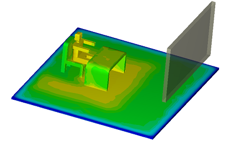
In the following results image, we see the effect of solar radiation passing through a window opposite the occupant. The higher temperature regions on the floor are from solar radiation entering the space. The lower temperature behind the chair is caused by the shadow cast by the desk and occupant:
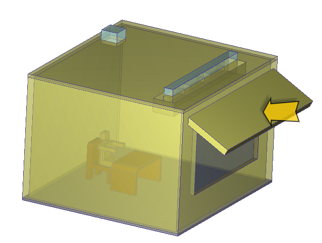
In this image, we've added an awning to the outside of the structure to partially block the sunlight from passing through the window. Note the difference in the temperature footprint on the floor caused by the reduction of solar energy entering the room:

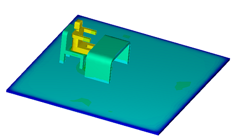
To contrast, we've disabled solar radiation from the simulation in the following image. The window was replaced with an opaque wall, and a constant film coefficient applied to all wall surfaces. Because there is no shadowing effect due to solar radiation passing through the window, the temperature is uniform across the floor:
Modeling Guidelines
You should follow standard modeling practices when simulating solar effects within occupied spaces.
- In an AEC Solar simulation, this means that there must be an air volume.
- Typically there are internal objects as well (occupants, furniture, etc.).
- Model walls as 3D volumes.
- Model windows as 3D volumes.
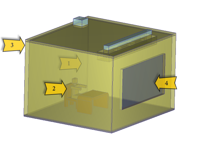
To include an awning to deflect sunlight, add a volume or part to the outside of the structure. It does not contact any fluid, but does block solar radiation, thus casting a shadow.
Simulation Settings
Materials
To account for solar radiation on exterior surfaces, assign a solid material to external parts, and modify the Transmissivity property.
- For opaque walls, doors, and awnings, select Solar Wall as the Transmissivity Variation method.
- For windows and other transparent surfaces such as skylights, select Solar Window as the Transmissivity Variation method.
Input the values for SHGC and U-Factor. These quantities are defined as:
- SHGC: This is the Solar Heat Gain Coefficient, and is the fraction of solar radiation admitted through a window, door, or skylight. It can be transmitted directly, as well as absorbed and released as heat inside the occupied space. Lower values of SHGC indicate less solar heat is transmitted and better shading. A product with a low SHGC rating is more effective at reducing cooling loads during the summer by blocking heat gain from the sun. Higher SHGC ratings indicate more effective solar heat collection during the winter. The climate, orientation, and external shading determine the optimal SHGC for a particular window, door, or skylight.
- U-factor: The rate at which a window, door, or skylight conducts non-solar heat flow. For windows, skylights, and glass doors, a U-factor may refer to just the glass or glazing alone. NFRC U-factor ratings, however, represent the entire window performance, including frame and spacer material. The lower the U-factor, the more energy-efficient the item.
Source: http://energy.gov/energysaver/articles/energy-performance-ratings-windows-doors-and-skylights
For Solar Walls, only a U-Factor is needed. For Solar Windows, you should specify both a U-factor and SHGC value.
The U-factor and the temperature difference computed during the calculation are used to compute the effective conductivity of the solid, and automatically override the thermal conductivity property assigned to the material.
There are two Solar materials in the Default material library that you can use with your simulations or as templates for your own solar materials. Both have appropriate SHGC and U-factor values prescribed for the Transmissivity:
- Window (solar): This is a modified version of the Glass solid material. The SHGC = 0.3, and the U-factor is 0.35 BTU/hr-ft2-F. These are typical values for residential double paned windows installed in mixed/southern (zone 6-8) climates.
- Wall (solar): This is a modified version of the Insulation (fiberglass) solid material. The SHGC = 0, and the U-factor is 0.1 BTU/hr-ft2-F. These are typical values for residential wall construction with fiberglass insulation in climate zone 6-8.
The Solve dialog and Solar heating dialog
Enable the following on the Solve dialog:
- Heat Transfer
- Radiation
- If you expect natural convection effects, and have enabled Variable on the Material Environment dialog, specify a Gravity Direction.
Click the Solar heating button. On the Solar Heating dialog, enable the following:
- The Location that you are simulating. If the location is not listed in the Country and City fields, check Manual, and enter the Latitude and Longitude.
- The Date and Time that you are simulating.
- The Orientation of the model. Use the Axes displayed on the simulation model to help you define these directions.
- The Ambient Reference. This temperature is applied to all exterior surfaces of Solar Walls and Solar Windows. Note that thermal boundary conditions such as film coefficient, temperature, heat flux, and total heat flux that are applied to the exterior surfaces of Solar Walls and Solar Windows operate as prescribed, and override the Ambient Reference temperature.
- The Time variation of the Ambient Reference. If you select Steady State, specify a single value. If you select Transient, specify the Time-Temperature relationship with the Time Curve.
Viewing AEC Solar Results
The two result quantities that provide the greatest insight for solar heating simulations are Temperature and Solar Heat Flux. Autodesk® CFD automatically enables Solar Heat Flux for solar heating simulations. It is best to view Solar Heat Flux as a global quantity as it appears on surfaces of the model. In the following examples, we display Solar Heat Flux on the models with and without an awning. In both cases, the simulated time and date is noon in early December, and the location is in the Mid-Atlantic region of the United States:
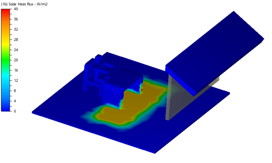
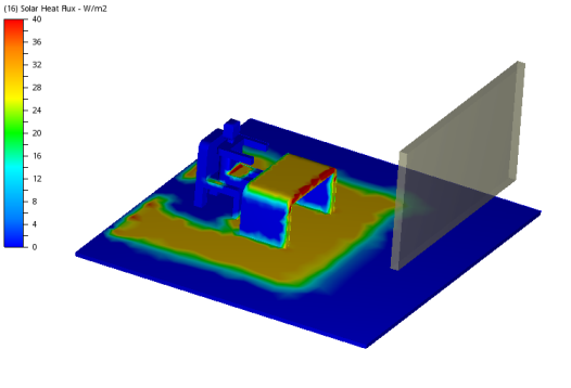
In both cases the sun is low on the horizon, and casts a long footprint on the floor. In the case with the awning, much of the sunlight is blocked, and the solar footprint appears only in front of the desk. Without the awning, the footprint extends through the room, and there is a shadow behind the occupant.