Use this procedure to place a callout that creates a detail in an existing project view drawing.
- On the Quick Access toolbar, click
 .
. - Click the Views tab.
- Select the view drawing in which you want to place the detail callout, right-click, and click Open.
- On the Tool Palettes, click
 (Properties), and click Document.
 - Click the Callouts palette.
- Select a detail callout tool:
If you want to… Then… create a callout with a detail boundary and a detail mark select one of the detail boundary tools. AutoCAD Architecture toolset provides tools for circular, rectangular, and freeform detail boundaries. create a callout without a detail boundary select one of the detail mark tools. AutoCAD Architecture toolset provides tools for regular detail marks, detail marks with a tail, and detail marks with a sheet number attribute. Alternatively, you can click


 for callouts with a detail boundary, or


 for callouts without a detail boundary.
 - If you selected a detail boundary tool, specify the extents of the detail boundary.
- Specify the detail leader line, and press Enter.
- Under New Model Space View Name, enter a name for the new model space view containing the detail.
- If necessary, select Generate Section/Elevation.
- If you want to add a title mark to the new model space view, select Place Titlemark.
- Select the scale for the model space view.
- Click Existing View Drawing.

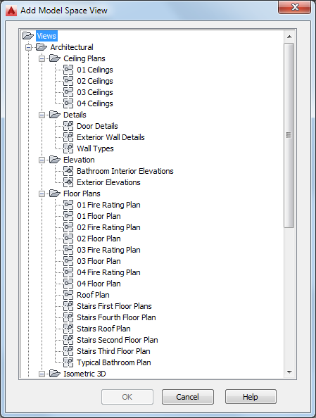
Select a drawing to place the detail
- Select the project view drawing in which to place the model space view, and click OK.
- If you selected to create a detail with a section/elevation, specify the insertion point of the 2D section/elevation result.
- If you selected to create a detail without a section/elevation, specify the extents of the model space view containing the area being detailed.
The extents of the model space view will dictate the default sheet view size, so if the model space boundary is too small, you may have problems placing annotations in it.
Once the model space view has been placed in the drawing, the field placeholders in the callout change to a question mark. To resolve them, the model space view needs to be placed onto a sheet.
- To display the model space view in the Project Navigator, navigate to the target drawing, and expand it.
The model space view is listed under the drawing.