You can convert a single AutoCAD block, MvBlock, or MvPart to a device. Because devices are style-based objects, and all style-based objects are defined by styles, this creates an associated device style as well.
To convert a block or part to a device
- Select the AutoCAD block, MvBlock, or MvPart to convert to a device.
You can select a block or part in the current drawing or in one of its referenced drawings (xrefs).
- Click
 .
.
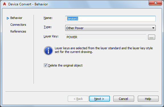
- In the Device Convert - Behavior dialog box, for Name, enter a unique name for the device, and for Type, select the type of device to create. Tip: The Type property of the device can be useful when you need to modify multiple objects of the same type. You can quickly select all of the objects in the drawing, and then use a modify command, such as LIGHTINGMODIFY, to modify only the objects of a specific type.
- For Layer Key, click
 to open the Select Layer Key dialog box, select the layer key to associate with the device, and click OK.
 The list of layer keys from which you can select is determined by the layer standard and layer key style that is specified for the current drawing.
Note: Since you are creating a device and an associated device style using this process, the layer key determines not only the layer key for the individual device, but also the layer key defined in the device style. - Click Delete the original object to replace the old object with the newly converted one.
- Click Next.
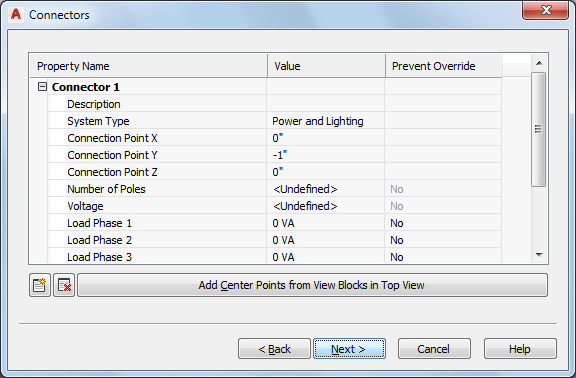
- Specify values for the electrical connectors on the device:
If you want to… then… enter a description for the connector enter the text in Value column for Description. Use a descriptive phrase that identifies what the connector represents, such as Normal Power. specify a type of circuit for the connector select a system type for System Type. Note: If you select Power and Lighting, you can configure additional connector properties, such as voltage and load.center the connector on the device click Add Center Points from View Blocks in Top View. specify the X, Y, and Z values for the connector enter values for Connection Point X, Connection Point Y, and Connection Point Z. add a connector click  .
. remove a connector select the connector, and click  .
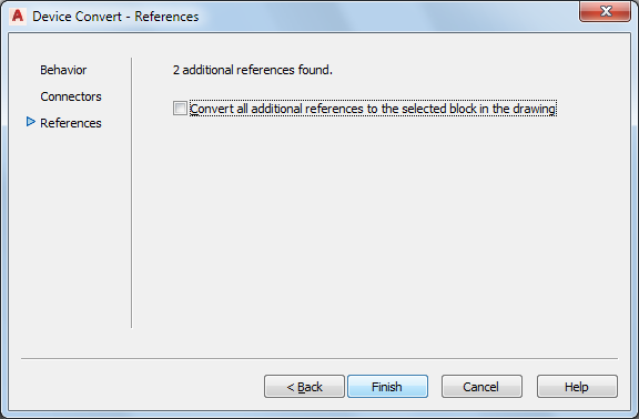
. - If the software finds no other additional blocks or parts of the same type as the one you are converting, you can click Finish to convert the object. Otherwise, click Next.
- If you want to convert the additional blocks or parts to devices that have the same properties, select Convert all additional references to the selected block in the drawing, and click Finish.
Using the settings that you specified as well as the AutoCAD block or the view block currently assigned to the MvBlock or MvPart, the software creates a device style and a new device. However, the device style contains additional settings that you might want to configure. For example, you might want to select a wire cleanup method other than the default method; you might also want to make changes to the default view definitions.
Tip: After you have configured the device and the device style with the appropriate settings, you can create a tool from the device by dragging it to a tool palette.