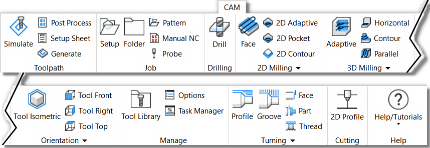
- Inventor CAM Express - 2D/2.5 axis Milling functions for general machining.
- Inventor CAM Premium - 2D and 3D Milling, 3+2 Milling and Turning functions.
- Inventor CAM Ultimate - 2D, 3D, 3+2 Milling, 5x simultaneous Milling and Turning functions.
The command ribbons and the commands they offer for the three different versions of Inventor CAM appear below:

The Inventor CAM Express command ribbon |
The Inventor CAM Premium command ribbon |
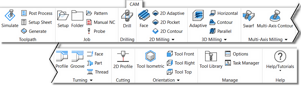
The Inventor CAM Ultimate command ribbon |
Successful Toolpath Creation
There are several steps you should follow to create your NC programmed part.
- Setup - Defines the part orientation, cutting plane, Stock size, XYZ Zero location and Work Coordinate System (WCS) offset.
- Toolpaths - Select the appropriate cutting strategy, cutting area, cutting tool and cutting steps.
- Simulation - Verify the toolpath meets your needs and cuts the correct areas. Edit the Toolpath Strategy if needed.
- Post Process - Select a Post that matches your machine/control and NC output for your machine.
Setup and ToolTips
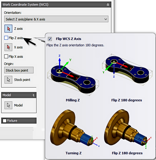
Setup lets you select the type of machine you will be programming, set your stock size and XYZ zero position. Since you can machine any face on the part, use the WCS parameters to align the axis to your part. ToolTips are a powerful tool for learning about the system parameters. Some ToolTips will have a simple description of the parameter, other will have illustrations to make the point. Hover your cursor over the parameter to see the ToolTip appear. The Illustration on the right shows the ToolTip for the "Flip Z Axis" parameter.

Toolpath Strategies and The CAM Browser
The CAM Browser is docked on the left side. It lets you view and modify the machining strategies associated with the current part. The CAM Browser becomes active once a part or assembly file is loaded and a toolpath strategy is selected from the CAM ribbon. This replaces the Autodesk Inventor Model Browser.
To create your first machining operation, simply select any of the toolpath strategies from the CAM toolbar. The type of toolpath required naturally depends on the geometry of your part. For a description of the individual machining strategies, please refer to the Inventor CAM Help topics: 2D Machining Strategies and 3D Machining Strategies.
After creating your Setup, you can select a Toolpath Strategy by clicking the appropriate icon from the command ribbon.
In this example lets pick
CAM tab  2D Milling panel
2D Pocket
2D Milling panel
2D Pocket
 .
.
You can also right-click in an empty portion of the graphics window to display the Inventor marking menu and then select the appropriate 2D Toolpath Strategy.

The Operation dialog box will display in the CAM Browser at the left side of the graphics window. In its title bar is the name of the strategy selected. Just to the right of the strategy name is the operation number. Since this is the first 2D pocket operation for the part, the name displays as 2D Pocket1. The next 2D pocket operation will display as 2D Pocket2, and so on. This naming convention applies to all setup and machining strategies in Inventor CAM.
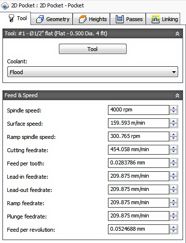
Toolpath Dialogs
All toolpath dialogs follow a similar format. You will find 5 Tabs at the top of the dialog. This is an over view of each tab.
|
Tool Tab
|
|
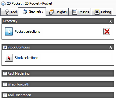
Geometry Tab
|
|
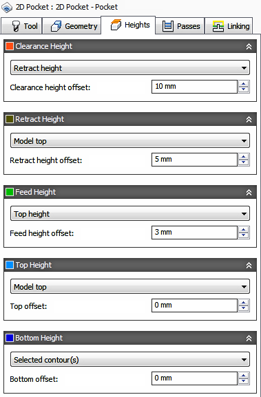
Heights Tab
If the Face or Edge you selected is the final cutting depth, no depth position needs to be specified. Most times you do not need to make any adjustments, depending on the geometry selected for machining. |
|
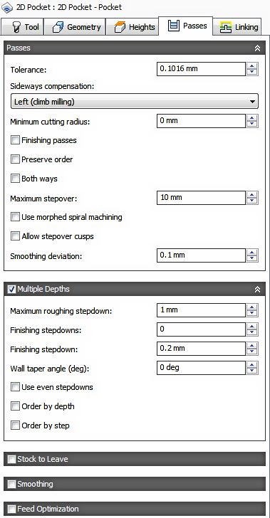
Passes Tab
|
|
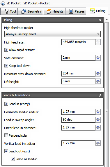
Linking Tab
|
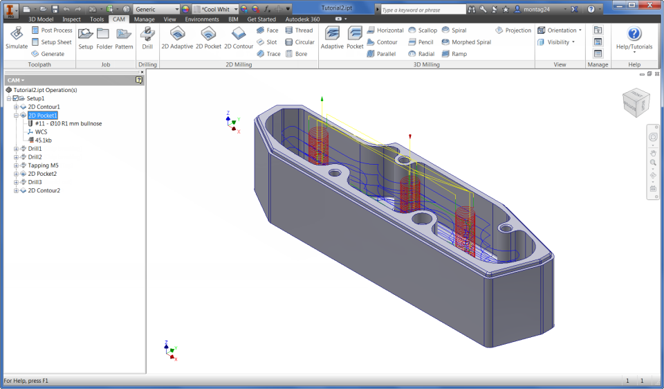
A view of the CAM Browser containing toolpaths, with the 2D Pocket toolpath selected.
Toolpath Simulation
To verify the toolpath, select one or more operations from the CAM Browser (multiple operations can be selected by pressing and holding the Ctrl key while clicking with the mouse), and then
CAM tab
Toolpath panel
Simulate
 on the CAM ribbon.
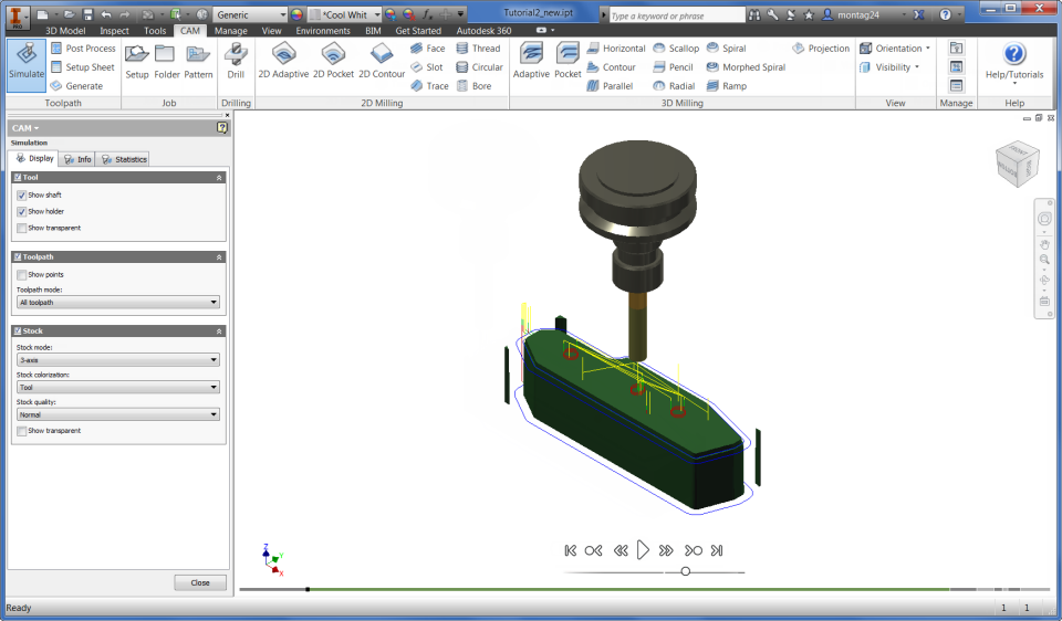
Stock Simulation
To invoke the solid simulation, enable the Stock check box in the Simulation dialog.
Use the player controls at the bottom of the graphics window to Play, Stop, Rewind or Step thru the toolpath simulation. The bottom slider controls the speed and direction (Forward or Backwards).
Post Processing
Inventor CAM ships with a number of customizable post processors that can be invoked by selecting one or more operations from the CAM Browser, and clicking
CAM tab
Toolpath panel
Post Process
 on the CAM ribbon.
Search thru the list for your Machine brand or Control brand. If you dont see your machine or control, click the link at the bottom of the dialog to visit our on-line Post Processor library.

Log Messages
If an operation in the CAM Browser is overlaid with an orange checkmark, it indicates that the operation could not be generated successfully. To see a description of the problem or error, right-click the operation and select Show Log from the pop-up context menu. The log is displayed in a dialog box and explains what went wrong.
Associativity and Regeneration
When you define operations in Inventor CAM, all relations to the model are associative. That means that if you change your model, you will not have to redefine any parameters and selections again - they will persist across model changes and rebuilds. You will, however, have to regenerate your operation whenever a part of the model is modified on which the operation depends.
When a modification of the model triggers invalidation of a toolpath, the regeneration symbol (i.e. a red cross) is overlaid on the corresponding operation and toolpath nodes in the CAM Browser. If you try to use an invalidated toolpath, you are notified that it requires regeneration.
Toolpath panel
Generate
 from the CAM ribbon regenerates all operations that require regeneration.
While regenerating toolpaths, the
Inventor CAM
Task Manager dialog is shown. This shows the progress of any ongoing toolpath calculation, but can be hidden by clicking the
Hide button so that you can continue working while the regeneration completes. Normally, 2D toolpaths generate in a matter of seconds, but some of the 3D strategies can take a considerable time to calculate, depending on the geometry and tolerances. If you have hidden the
Task Manager dialog, you can restore its visibility by clicking
CAM tab
Manage panel
Task Manager
 .
.