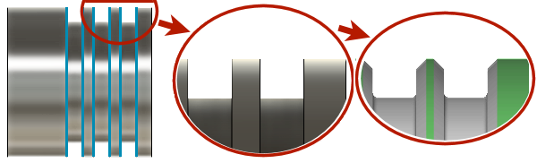
The Chamfer strategy is used for chamfering sharp corners that have not been chamfered in the design.
|
Access: |
Ribbon:
CAM tab
 Turning panel
Chamfer
Turning panel
Chamfer

|
 Tool tab settings

Tool
Select a tool from the library, or create a new tool.
Coolant
Select the type of coolant that should be used with the tool. Output options will vary depending on the machine capabilities and machine postprocessor configuration.
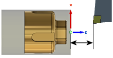
Use Tailstock
A tailstock can be used to support the open end of the workpiece. This is particularly useful when the workpiece is relatively long and slender, or large and heavy. Failing to use a tailstock can cause the workpiece to flex while being cut, causing poor surface finish (chatter) and inaccuracies.
For this option to take effect, your machine needs a programmable tailstock and your post processor has to be configured to write the code your specific machine needs. Once configured, the post will output the appropriate code to extend the tailstock forward at the beginning of the operation and retract the tailstock backward at the end of the operation.
Turning Mode
Determines whether the tool machines on the Outside Diameter or Inside Diameter, as well as the controlling the approach/retract direction.
Outside Chamfer (top) - Inside Chamfer (bottom)
- Outside chamfering - The tool approaches from/retracts to the outside of the stock and machines towards the parts center line.
- Inside chamfering - The tool approaches from/retracts to the inside of the stock and machines away from the parts center line.
Tool Orientation
 |
|
|
Tool Orientation @ 45 degrees. |
Tool Orientation @ 90 degrees. |
Use constant surface speed
Enable to automatically adjust the spindle speed to maintain a constant surface speed between the tool and the workpiece as the cutting diameter changes . Constant Surface Speed (CSS) is specified using G96 on most machines.
Surface Speed
The cutting speed expressed as the speed of the tool across the part surface. Expressed as Ft/min or M/min depending on the current Units setting.
Spindle Speed
The rotational speed of the spindle.
Maximum Spindle Speed
Specifies the maximum allowed spindle speed when using Constant Surface Speed (CSS).
Use Feed per Revolution
Enable to switch from Distance over Time (In/Min or MM/min), to Feed Per Revolution (IPR or MMPR). This type of feedrate creates a constant chip load regardless of the spindle RPM.
Cutting Feedrate
Feed used in cutting moves. Input based on the Use Feed per Revolution setting and the current Units.
Lead-In Feedrate
Feed used when leading in to a cutting move. Input based on the Use Feed per Revolution setting and the current Units.
Lead-Out Feedrate
Feed used when leading out from a cutting move. Input based on the Use Feed per Revolution setting and the current Units.
 Geometry tab settings
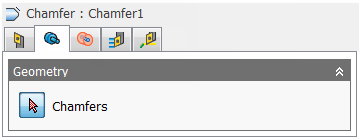
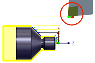
Chamfers
Use the Chamfers selection button to select one or more circular edges for chamfer creation.
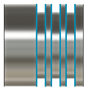
Edge selection shown in blue
 Radii tab settings
|
|
|
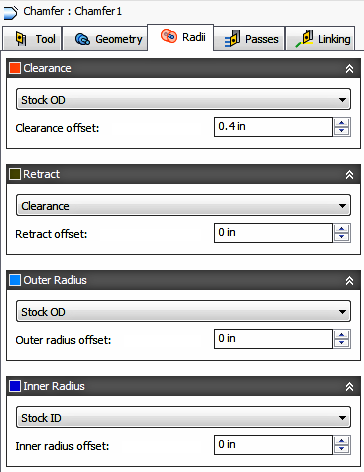
Radii Options for Outside Turning . |
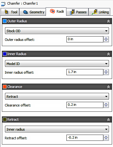
Radii Options for Inside Turning. |
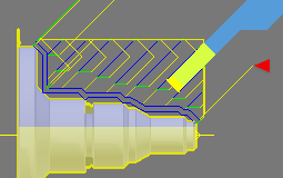
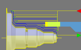
The Radii tab allows you to set a radial containment area for machining. The dialog will change depending on if the Turning Mode (Tool tab parameter) is set to Outside chamfering or Inside chamfering. These parameters are color coded for easy identification.

|

|
Order for Outside Turning. |
Order for Inside Turning. |
Clearance
Shown in Orange, this controls the radius where the tool rapids to at the start and end of the toolpath. For OD machining this position is outside the part. For ID machining this position is from an inside tube or bore. The tool approaches from and retracts to this position.
Shown in Orange, "From" sets the Clearance radius reference position. The reference can be in relation to the Stock, the Model, a specified Radius, Diameter, or any of the other Radial positions. This reference position can be shifted with a positive or negative offset value.
- Retract - Sets the Clearance radius in reference to the Retract Position.
- Stock OD- Sets the Clearance radius in reference to the outside diameter of the defined Stock.
- Model OD - Sets the Clearance radius in reference to the outside diameter of the defined Model.
- Outer radius - Sets the Clearance radius in reference to the Outer radius position. The Clearance radius must be larger than the Outer radius. Use the Offset parameter to make adjustments as needed.
- Inner radius - Sets the Clearance radius in reference to the Inner radius position. The Clearance radius must be larger than the Inner radius. Use the Offset parameter to make adjustments as needed.
- Model ID - Sets the Clearance radius in reference to the inside diameter of the Model, as defined in the Setup. Use the Offset parameter to make adjustments as needed.
- Stock ID - Sets the Clearance radius in reference to the inside diameter of the Stock, as defined in the Setup. Use the Offset parameter to make adjustments as needed.
- Selection - Select any face, vertex, or point on the model to define the Clearance radius. Use the Offset parameter to make positive or negative adjustments as needed..
- Radius - This option allows you to enter a radius value in the Offset field. This value is in reference to the centerline of the part and will not recognize any associative changes to the model.
- Diameter - This option allows you to enter a diameter value in the Offset field. This value is in reference to the centerline of the part and will not recognize any associative changes to the model.
Offset
Use this offset to shift the position relative to the Reference point selected above. You can make positive or negative adjustments as needed.
|
|
|
For Outside Turning. |
For Inside Turning. |
Retract
Shown in Dark Green, this controls the position above the surface you plan to machine. This is the radius where the tool retracts to between cuts.
Shown in Dark Green, "From" sets the Retract reference position. The reference can be in relation to the Stock, the Model, a specified Radius, Diameter, or any of the other Radial positions. This reference position can be shifted with a positive or negative offset value.
- Clearance - Sets the Retract radius in reference to the Clearance Position.
- Stock OD- Sets the Clearance radius in reference to the outside diameter of the defined Stock.
- Model OD - Sets the Clearance radius in reference to the outside diameter of the defined Model.
- Outer radius - Sets the Clearance radius in reference to the Outer radius position. The Clearance radius must be larger than the Outer radius. Use the Offset parameter to make adjustments as needed.
- Inner radius - Sets the Clearance radius in reference to the Inner radius position. The Clearance radius must be larger than the Inner radius. Use the Offset parameter to make adjustments as needed.
- Model ID - Sets the Clearance radius in reference to the inside diameter of the Model, as defined in the Setup. Use the Offset parameter to make adjustments as needed.
- Stock ID - Sets the Clearance radius in reference to the inside diameter of the Stock, as defined in the Setup. Use the Offset parameter to make adjustments as needed.
- Selection - Select any face, vertex, or point on the model to define the Clearance radius. Use the Offset parameter to make positive or negative adjustments as needed..
- Radius - This option allows you to enter a radius value in the Offset field. This value is in reference to the centerline of the part and will not recognize any associative changes to the model.
- Diameter - This option allows you to enter a diameter value in the Offset field. This value is in reference to the centerline of the part and will not recognize any associative changes to the model.
Offset
Same function as the Clearance Offset shown above.
Outer Radius
Shown in Light Blue, this defines the largest radial boundary of the cutting area. For Outside (OD) machining, Outer Radius defines the outer stock surface you plan to machine. For Inside (ID) machining, Outer Radius controls the maximum depth for the cut area.

|

|
|
For Outside Turning. |
For Inside Turning. |
Shown in Light Blue, "From" sets the Outer Radius reference position. The reference can be in relation to the Stock, the Model, a specified Radius, Diameter, or any of the other Radial positions. This reference position can be shifted with a positive or negative offset value.
- Clearance - Sets the Retract radius in reference to the Clearance Position.
- Retract - Sets the Clearance radius in reference to the Retract Position.
- Stock OD- Sets the Clearance radius in reference to the outside diameter of the defined Stock.
- Model OD - Sets the Clearance radius in reference to the outside diameter of the defined Model.
- Inner radius - Sets the Clearance radius in reference to the Inner radius position. The Clearance radius must be larger than the Inner radius. Use the Offset parameter to make adjustments as needed.
- Model ID - Sets the Clearance radius in reference to the inside diameter of the Model, as defined in the Setup. Use the Offset parameter to make adjustments as needed.
- Stock ID - Sets the Clearance radius in reference to the inside diameter of the Stock, as defined in the Setup. Use the Offset parameter to make adjustments as needed.
- Selection - Select any face, vertex, or point on the model to define the Clearance radius. Use the Offset parameter to make positive or negative adjustments as needed..
- Radius - This option allows you to enter a radius value in the Offset field. This value is in reference to the centerline of the part and will not recognize any associative changes to the model.
- Diameter - This option allows you to enter a diameter value in the Offset field. This value is in reference to the centerline of the part and will not recognize any associative changes to the model.
Offset
Same function as the Clearance Offset shown above.
Inner Radius
Shown in Dark Blue, this defines the smallest radial boundary of the cutting area. For Outside (OD) machining, Inner Radius controls the maximum depth for the cut area . For Inside (ID) machining, Inner Radius defines the inner stock surface you plan to machine.
|
|
|
|
For Outside Turning. |
For Inside Turning. |
Shown in Dark Blue, "From" sets the Inner Radius reference position. The reference can be in relation to the Stock, the Model, a specified Radius, Diameter, or any of the other Radial positions. This reference position can be shifted with a positive or negative offset value.
Same as the Outer Radius "From" options shown above.
Offset
Same function as the Clearance Offset shown above.
 Passes tab settings
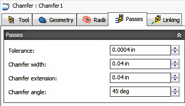
Tolerance
Also known as the Cut Tolerance, this Tolerance is for toolpath generation and geometry triangulation. Any additional filtering tolerances, like Smoothing, must be added to this tolerance to get the Total Tolerance for the cut..
 |
 |
|
Loose Tolerance .100 |
Tight Tolerance .001 |
CNC machine motion is controlled using G1 line and G2 G3 arc commands. To accommodate this, Inventor CAM approximates spline and surface toolpaths by linearizing them; creating many short line segments to approximate the desired shape. How accurately the toolpath matches the desired shape depends largely on the number of lines used. More lines result in a toolpath that more closely approximates the nominal shape of the spline or surface.
Data Starving
A tighter tolerance will result in a more accurate path with smaller line segments. It is tempting to always use very tight tolerances, but there are trade-offs including longer toolpath calculation times, large G-code files and very short line moves. Each can be a problem depending on your situation. Inventor CAM will calculate quickly on almost any computer. But if you have an older NC control with limited memory and a machine with slower axis drives, the toolpath motion might appear jumpy. This is a phenomenon known as data starvation. This Tolerance, along with Smoothing, can reduce your program size and improve your machines performance.
Data starving occurs when the control becomes so overwhelmed with data that it cannot keep up. CNC controls can only process a finite number of lines of code (blocks) per second. That can be as few as 40 blocks/second on older machines and 1,000 blocks/second or more on a newer machines. Short line moves and high feedrates can force the processing rate beyond what the control can handle. When that happens, the machine must pause after each move and wait for the next servo command from the control.
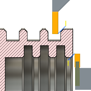
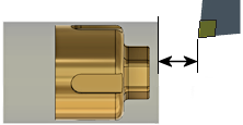
Chamfer Width
The (additional) width of the chamfer. For edges that are not already chamfered, this is the final width of the chamfer. (illustration shown below)
If you selected an edge that already has a chamfer, this is the additional amount to chamfer the edge.
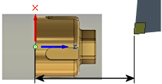
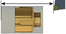
Chamfer Extension
Distance to extend the chamfer cutting pass, past the chamfer edge. (illustration shown below)
Chamfer Angle
The angle of the chamfer measured from the Z-axis. (illustration shown below)
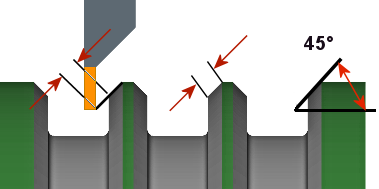
Shown left to right: Extension - Chamfer Width - Angle
Stock to Leave
| Positive Stock to Leave
The amount of stock left after the operation is completed. This can be removed by subsequent roughing or finishing operations. It's common to leave a small amount of material after a roughing operation. |
 |
| No Stock to Leave
Remove all excess material up to the selected geometry. |
 |
| Negative Stock to Leave
Removes material beyond the part surface or boundary. |
 |
Radial (OD/ID) Stock to Leave - Axial (face) Stock to Leave
The Radial Stock to Leave parameter controls the amount of material to leave in the radial direction, i.e. Outside Diameter or Inside Diameter. Specifying a positive Radial stock to leave results in material being left on the OD or ID of the part.
The Axial Stock to Leave parameter controls the amount of material to leave in the axial direction (along the Z-axis), i.e. On the faces of flanges. Specifying a positive Axial stock to leave results in material being left on the Faces and shallow areas in the Z direction.
Changing the Radial stock amount automatically sets the Axial stock to the same value. You can manually enter a different Axial stock amount to leave. When using unequal amounts of stock, surfaces that are not exactly horizontal/vertical, Inventor CAM interpolates between the axial and radial stock amounts. So the stock left on these surfaces might be different from the specified value, depending on surface slope.

|

|
|
Axial stock to leave |
Radial stock to leave |
For finishing operations, it's common to set the default value to 0 mm / 0 in, i.e. no material is left.
For roughing operations, it's common to leave a small amount of material that can then be removed later by one or more finishing operations.
Negative stock to leave
When using a negative stock to leave, the machining operation removes more material from your stock than your model shape. This can be used to machine electrodes with a spark gap, where the size of the spark gap is equal to the negative stock to leave.
Both the radial and axial stock to leave can be negative numbers. However, the negative radial stock to leave must be less than the tool radius. When using a large nose radius or a button type insert with a negative stock, the negative stock must be less than or equal to the radius.
 Linking tab settings

Retraction Policy
Controls how the tool should retract to the clearance diameter after every cutting pass. or just retract a short distance away from the job. The distance is determined by the Safe Distance value.
 |
 |
| Full retraction - completely retracts the tool to the Retract Height at the end of the pass before moving above the start of the next pass. | Minimum retraction - moves straight up to the lowest height where the tool clears the workpiece, plus any specified safe distance. |
High Feedrate Mode
Specifies when rapid movements should be output as true rapids (G0) and when they should be output as high feedrate movements (G1).
- Preserve rapid movement - All rapid movements are preserved.
- Preserve axial and radial rapid movement - Rapid movements moving only horizontally (radial) or vertically (axial) are output as true rapids.
- Preserve axial rapid movement - Only rapid movements moving vertically.
- Preserve radial rapid movement - Only rapid movements moving horizontally.
- Preserve single axis rapid movement - Only rapid movements moving in one axis (X, Y or Z).
- Always use high feed - Outputs rapid movements as (high feed moves) G01 moves instead of rapid movements (G0).
This parameter is usually set to avoid collisions at rapids on machines which perform "dog-leg" movements at rapid.
High Feedrate
The feedrate to use for rapids movements output as G1 instead of G0.
Approach and Retract
Used to define how the tool should position at the start of the operation and the end of the operation. The default position is in reference to the Safe Z as defined in the Setup. You can override the Setup Safe Z position with the options shown below.
- Safe Z - The Approach position will be the same as the Safe Z position defined in the Setup.
- First Toolpath Position - The Approach position will be the same as the first Z position of the toolpath.
Approach Z - Defines how the tool will position before the start of the toolpath.
- Safe Z - The Approach position will be the same as the Safe Z position defined in the Setup.
- Last Toolpath Position - The Retract position will be the same as the Last Z position of the toolpath.
Retract Z - Defines how the tool will position after completing the toolpath.
Override Setup Safe Z
Enable to redefine the Reference position for the Safe Z retract.
- Setup WCS Origin - Set reference to the Work Coordinate Offset position set in the Setup
- Stock Front - Set the reference to the Stock Font position
- Stock Back - Set the reference to the Stock Back position
Safe Z Reference - Select the new reference position to set the Safe Z retract.
Safe Z Offset
Set the distance to shift from the reference position specified above.
WCS Reference and Offset Distance |
WCS Reference and Offset Distance |
Stock Front Reference and Offset Distance |
Stock Back Reference and Offset Distance |