Overview of the Toolpath Operations dialogs and the Tab structure.
The tabs on the Operation dialog box share a similar layout for all milling operations. The machining settings are grouped into five tabs that provide a quick way to navigate between the settings and greatly reduces the amount of scrolling required.
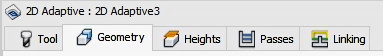
This image shows The active Geometry tab in the Operation dialog for a 2D Adaptive operation.
 Tool tab
Select a tool for the operation. You can also edit the tool in the Tool Library and set the feeds and speeds for the operation.
 Geometry tab
- Geometry - Item or area top machine
- Machining Boundary - Containment area to restrict machining
- Slope - For 3D toolpath to represent changes in the part curvature
- Rest Machining - Options for removing previously uncut material
- Tool orientation - Can be used to reorient the tool for 4th axis indexing and 3+2 machining
- Model - Where several models exist, use this to select the model to considered by this toolpath strategy
- Avoid/Touch Surfaces - Select areas to avoid machining
 Heights tab
- Clearance Height - The first height the tool rapids to, on its way to the start of the tool path
- Retract Height - The height that the tool moves up to before the next cutting pass
- Feed Height - The height that the tool moves to before feeding into the part
- Top Height - The height that describes the top of the cut
- Bottom Height - The final machining depth that the tool descends into the stock
 Passes tab
- Tolerance - Calculated accuracy for the cut
- Stepover - Amount to step for the side cutting motion
- Stepdown - Amount to step down per cut
- Stock to Leave - Stock to leave for future machining processes
- Fillets - Automatic blending of sharp corners
- Smoothing - Line and Arc filtering. Turns multiple small segments into a single line or arc
 Linking tab
- Retraction policy - Controls how the tool will retract between cutting moves
- Safe distance - Minimum distance between the tool and the part surfaces during retract moves
- Lead-in / Lead-out - Specifies how the tool will blend onto and off of the cut
- Ramping - Specifies how the cutter moves down for each depth cut
- Transitions - How to enter into the stock material
- Entry position(s) - Select a location to start or enter into the cut
Operation Dialog Position Options
Normally, the Operation dialog box shares the same space as the CAM Browser. You can separate the Operation dialog from the CAM Browser so that it can float freely or be docked to a more convenient location by doing the following:
- On the ribbon, click
Ribbon:
CAM tab
 Manage panel
Options
Manage panel
Options
 . The
CAM Options dialog box is displayed.
. The
CAM Options dialog box is displayed.
- Click the User Interface tab.
- Deactivate the Combine Operation dialog with CAM Browser check box.
- Click OK to exit the CAM Options dialog box.
The next time a machining strategy is selected, the Operation dialog box will display independent of the CAM Browser.
Making and Resetting Parameter Defaults
As far as possible, Inventor CAM provides working default values for each of the strategy parameters found in the Operation dialog box. You can control the default values of each parameter by right-clicking over the parameter name to display the pop-up context menu shown below.
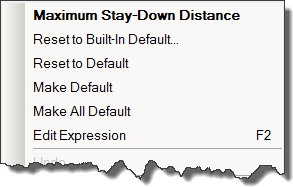
The current parameter name (in bold) is displayed at the top of the pop-up context menu. The remaining menu items offer the following options:
- Reset to Built-in Default - Resets the current field's expression to the out-of-the-box (system) default. This option ignores any user-saved default.
- Reset to Default - Resets the current field's expression to the user-saved default for the parameter/strategy.
- Make Default - Sets the current field's expression as the default for the corresponding parameter/strategy combination.
- Make All Default - Sets all of the current object's expressions as the defaults for the corresponding strategy.
- Edit Expression - Most of the parameters in
Inventor CAM have default values based on expressions involving other parameters, such as the tool diameter (referenced by tool diameter in an expression). You can enter a new expression directly in the parameter field or you can modify an existing expression using the
Expression dialog box by selecting
Edit Expression from the pop-up context menu or by pressing function key
F2.
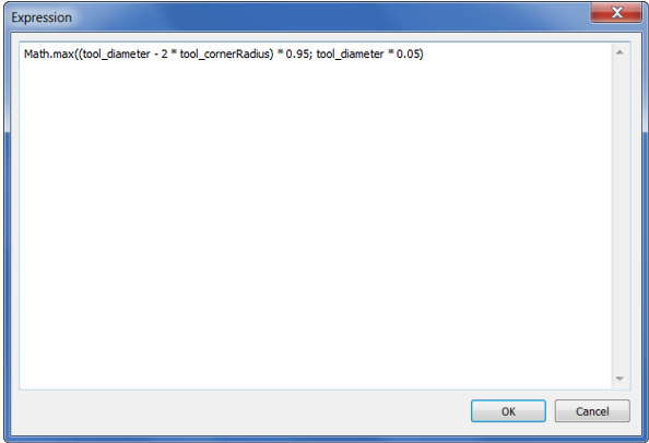
The Expression dialog box
The names for referencing other parameters can be determined by holding down the Shift key while hovering your mouse over a parameter field.
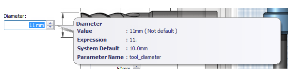
Parameter names are shown in the tooltip when holding Shift