A process for creating a variety of hole types like drilling, tapping and boring.
|
 |
|
Access: |
Ribbon:
CAM tab
 Drilling panel
Drill
Drilling panel
Drill

|
Drilling is a common machining task for creating holes in the work piece. This function will usually trigger the CNC controls Canned Cycles. These cycles incorporate the common motion used for a specific hole machining task. There are usually Canned Cycles for basic drilling, deep hole drilling, counter boring, boring and tapping. The canned cycle output in the final code depends on the postprocessor and your machines capabilities.
These are the types of drilling motion you can perform with this toolpath :
- Drilling - G81 style drilling with rapid out.
- Counterboring - G82 style drilling with dwell at bottom and rapid out.
- Chip breaking - Chip breaking with pecking and partial retracts between pecks.
- Deep drilling - Deep drilling with pecking and full retract between pecks.
- Guided deep drilling - gun drilling - Deep drilling that produces a very round hole with a precision diameter. Very useful for deep, straight holes in a variety of materials.
- Tapping - Tapping (G84/G74). Synchronous spindle speed and feed.
- Tapping with chip breaking - Tapping with chip breaking.
- Break through - Allows for reduced feed and speed before breaking through a hole.
- Reaming - Reaming (G85 style) with feed out.
- Boring - Boring with dwell at bottom and feed out.
- Stop boring - Boring (G86 style) with spindle stop at the bottom and rapid out.
- Fine boring - Fine boring with shift away from the hole side.
- Back-boring - Boring from the back.
- Circular pocket milling - Circular pocket milling.
- Bore milling - Bore milling.
- Thread milling - Thread milling.
- Probe - Used to measure a feature on the part with a probe tool, or use macros from the machine to define the WCS. Needs special handling in the post processors depending on the machine.
The input geometry for these cycles can be selected directly from the features of part geometry, and consistent with other 2D operations, input geometry can also be selected from a sketch, (for example: center points of arcs).
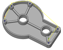
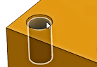
When working with solid models, the easiest way to use Drilling is to select the cylindrical faces of the holes. This automatically sets the correct stock height and depth for each hole. Drilling will recognize holes with different starting heights and depths, to create a single drill operation. Notice that when from cylindrical faces, the Select Same Diameter option is available. This allows easy - automatic - selection of any similar holes.
 Tool tab settings
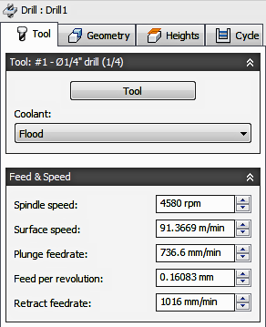
Coolant
Select the type of coolant used with the machine tool. Not all types will work with all machine postprocessors.
Feed & Speed
Spindle and Feedrate cutting parameters.
- Spindle Speed - The rotational speed of the spindle expressed in Rotations Per Minute (RPM)
- Surface Speed - The speed which the material moves past the cutting edge of the tool (SFM or m/min)
- Plunge Feedrate - The drilling feedrate when plunging into stock
- Feed per Revolution - The plunge feedrate expressed as the feed per revolution
- Retract Feedrate - Feed used when retracting, but not using rapid moves (G0)
 Geometry tab settings
|
|
|
Watch this short animation for an overview of the hole selection filters.
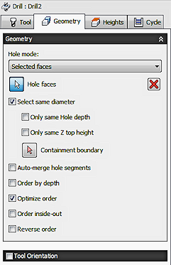
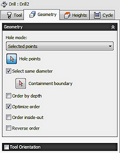
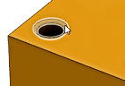
Hole Mode
Specifies which type of selections will be used for finding the drilling locations. Selecting Faces provides additional information like the starting height and hole depth. Selected Points will only return the XY location and Z starting height of the hole. Selected Faces is the preferred method for picking drilling locations because it maintains associativity to the Model Feature and will update the drilling operation if the model changes.
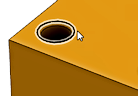
- Selected Faces - This is for Model based feature selection like cylinders or hole chamfers.
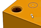
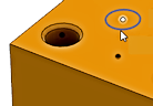
- Selected Points - This is for Geometry based hole selection like hole edges or Sketch geometry.
| Selected Faces - Cylinder | Selected Faces - Chamfer | |
|
|
|
| Selected Points - Hole Edge | Selected Points - Sketch Point | Selected Points - Sketch Circle |
|
|
|
Hole Faces
Contains the number of faces selected for drilling. This is for Model based feature selection. Use the X to clear all the currently selected items.
Hole Points
Contains the number of points or edge curves selected for drilling. This is for Geometry based hole selection. Use the X to clear all the currently selected items.
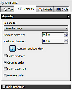
Diameter Range
Opens a parameter set for creating a minimum and maximum range selection. Eliminates the need to physically select features from the model. The system will evaluate the model based on the Minimum and Maximum Diameter values specified. Use this range to include or exclude hole sizes. This is useful If the part is modeled with sizes that represent different machining processes.
Example: Select all .250 - .2501 diameter holes for drilling and all .2505 - .2506 diameter holes for reaming.
- Minimum Range - Sets the range of the smallest diameter to select from the model.
- Maximum Range - Sets the range of the largest diameter to select from the model.
Tip: To Spot drill all the holes and create a chamfer - Select a Range for the holes to include. On the Heights tab, set the Bottom Height from Chamfer Width and set the desired Chamfer Width value. The depth will be based on the hole diameter + chamfer width.
Check to select all holes with the same diameter as the currently select feature.
A single selection will find all matching holes. Using this option is associative to the model. If additional holes with the same diameter are added later, regenerating the operation automatically includes the added holes in the drilling cycle.
Example: If you activate this option, select a single 6mm hole and a single 12mm hole, every 6mm and 12mm hole on the part will automatically be selected.
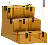
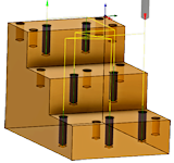
Only Same Hole Depth
Check to select all the holes that share the same top to bottom distance as the currently select feature.
Example: You can use this as a way to distinguish between 6mm tapped holes and 6mm drilled holes of different depths.
| Short Depth 6mm holes selected - ISO view | Short Depth 6mm holes selected - Front view |
|
|
| Long Depth 6mm holes selected - ISO view | Long Depth 6mm holes selected - Front view |
|
|
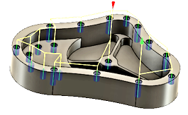
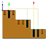
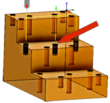
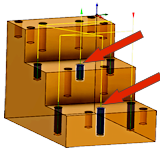
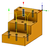
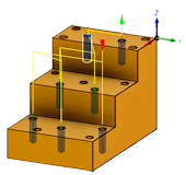
Only Same Z Top Height
Check to select all the holes that share the same Z top height as the currently select feature.
You can use this as a way to limit machining to one Z level. The red arrow below indicates the selected feature
|
All Short Depth Holes, at the Mid Level Height. |
All Short Depth Holes, at the Mid Level Height. All Long Depth Holes, at the Lower Level Height. |
|
|
Containment Boundary
Use this with Select Same Diameter and Diameter Range to include similar items inside the containment areas. Select any Edge or Sketch boundary to contain the drilling locations. Use multiple boundaries or nested boundaries, to include or exclude groups of holes. The toolpath will be inside the selected boundary unless the boundaries are nested. You can nest several boundaries inside each other.
In the examples below, the selected boundaries are shown in blue.

|
1) Sketch Boundaries 2) Holes inside are included 3) Nested Boundaries 4) Inside areas are excluded |
5) Sketch Boundaries (2) 6) Selecting the rim area only 7) Sketch Boundaries(3) 8) Excluding the rim area |
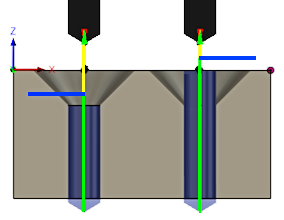
Check to merge multiple hole segments. When enable all hole segments are included to determine the starting height for drilling. Use this option when the selected drill hole has a counter bore. This will force the starting height to be at the top of the counter bored hole, rather than the top of the drilled hole.
'''Example''': If a hole was Spot Drilled or Counter Bored first, you may want to start drilling from a clearance above that machined area. Enabling Auto-Merge will start the drilling from above the highest hole segment.
|
Left Side Hole: Auto-Merge Disabled Right Side Hole: Auto-Merge Enabled Blue line indicates the starting height for drilling. |
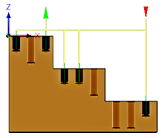
Order by Depth
Changes the order from the highest to lowest, or lowest to highest. Unchecked, the order will start with the holes at the highest Z level and progressively move down. Check to reverse the order.
|
When Unchecked. First hole is at the highest Z. |
When Checked. First hole is at the lowest Z. |
|
|
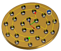
Optimize Order
When checked the path between holes is optimized for the shortest distance to reduce cycle time.
Order Inside-Out
Check to change the order of the toolpath to start at the inner most position of the part. Unchecked and the toolpath will start from an outside edge and work it's way across the part.
|
When Checked: First hole is at the inner most location. |
Tool Orientation
Allows you to redefine the machining plane, if it's different than the Tool Plane in the Setup and change the Work Coordinate System Origin (WCS - XYZ zero). The Tool Orientation sets the working XY machining plane and allows you to tilt the spindle axis (Z). This can be used for 4th axis indexing and 5 axis positioning. Also referred to as 3+2 axis position.
The Orientation drop-down menu provides the following options to set the orientation of the X, Y, and Z triad axes:
- Setup WCS orientation - Uses the workpiece coordinate system (WCS) of the current setup for the tool orientation.
- Model orientation - Uses the coordinate system (WCS) of the current part for the tool orientation.
- Select Z axis/plane & X axis - Select a face or an edge to define the Z axis and another face or edge to define the X axis. Both the Z and X axes can be flipped 180 degrees.
- Select Z axis/plane & Y axis - Select a face or an edge to define the Z axis and another face or edge to define the Y axis. Both the Z and Y axes can be flipped 180 degrees.
- Select X & Y axes - Select a face or an edge to define the X axis and another face or edge to define the Y axis. Both the X and Y axes can be flipped 180 degrees.
- Select coordinate system - Sets a specific tool orientation for this operation from a defined user coordinate system in the model. This uses both the origin and orientation of the existing coordinate system. Use this if your model does not contain a suitable point & plane for your operation.
The Origin drop-down menu allows you to shift the Work Coordinate System Origin (WCS - XYZ zero). It offers the following options for locating the origin:
- Setup WCS origin - Uses the workpiece coordinate system (WCS) origin of the current setup for the tool origin.
- Model origin - Uses the coordinate system (WCS) origin of the current part for the tool origin.
- Selected point - Select a vertex or an edge for the triad origin.
- Stock box point - Select a point on the stock bounding box for the triad origin.
- Model box point - Select a point on the model bounding box for the triad origin.
 Heights tab settings
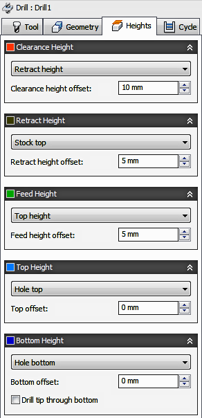
Clearance Height
The Clearance height is the first height the tool rapids to on its way to the start of the tool path.

Clearance Height
- Retract height: incremental offset from the Retract Height.
- Feed height: incremental offset from the Feed Height.
- Top height: incremental offset from the Top Height.
- Bottom height: incremental offset from the Bottom Height.
- Model top: incremental offset from the Model Top.
- Model bottom: incremental offset from the Model Bottom.
- Stock top: incremental offset from the Stock Top.
- Stock bottom: incremental offset from the Stock Bottom.
- Hole top: incremental offset from the Hole Top.
- Hole bottom: incremental offset from the Hole Bottom.
- Selection: incremental offset from a Point (vertex), Edge or Face selected on the model.
- Origin (absolute): absolute offset from the Origin that is defined in either the Setup or in Tool Orientation within the specific operation.
Clearance Height Offset
The Clearance Height Offset is applied and is relative to the Clearance height selection in the above drop-down list.
Retract Height
Retract height sets the height that the tool moves up to before the next cutting pass. Retract height should be set above the Feed height and Top. Retract height is used together with the subsequent offset to establish the height.

Retract Height
- Clearance height: incremental offset from the Clearance Height.
- Feed height: incremental offset from the Feed Height.
- Top height: incremental offset from the Top Height.
- Bottom height: incremental offset from the Bottom Height.
- Model top: incremental offset from the Model Top.
- Model bottom: incremental offset from the Model Bottom.
- Stock top: incremental offset from the Stock Top.
- Stock bottom: incremental offset from the Stock Bottom.
- Hole top: incremental offset from the Hole Top.
- Hole bottom: incremental offset from the Hole Bottom.
- Selection: incremental offset from a Point (vertex), Edge or Face selected on the model.
- Origin (absolute): absolute offset from the Origin that is defined in either the Setup or in Tool Orientation within the specific operation.
Retract Height Offset
Retract Height Offset is applied and is relative to the Retract height selection in the above drop-down list.
Feed Height
Feed height sets the height that the tool rapids to before changing to the feed/plunge rate to enter the part. Feed height should be set above the Top. A drilling operation uses this height as the initial feed height and the retract peck height. Feed height is used together with the subsequent offset to establish the height.

Feed Height
- Clearance height: incremental offset from the Clearance Height.
- Retract height: incremental offset from the Retract Height.
- Disabled: disabling the Feed Height causes the tool to rapid down to the lead-in.
- Top height: incremental offset from the Top Height.
- Bottom height: incremental offset from the Bottom Height.
- Model top: incremental offset from the Model Top.
- Model bottom: incremental offset from the Model Bottom.
- Stock top: incremental offset from the Stock Top.
- Stock bottom: incremental offset from the Stock Bottom.
- Hole top: incremental offset from the Hole Top.
- Hole bottom: incremental offset from the Hole Bottom.
- Selection: incremental offset from a Point (vertex), Edge or Face selected on the model.
- Origin (absolute): absolute offset from the Origin that is defined in either the Setup or in Tool Orientation within the specific operation.
Feed Height Offset
Feed Height Offset is applied and is relative to the Feed height selection in the above drop-down list.
Top Height
Top height sets the height that describes the top of the cut. Top height should be set above the Bottom. Top height is used together with the subsequent offset to establish the height.

Top Height
- Clearance height: incremental offset from the Clearance Height.
- Retract height: incremental offset from the Retract Height.
- Feed height: incremental offset from the Feed Height.
- Bottom height: incremental offset from the Bottom Height.
- Model top: incremental offset from the Model Top.
- Model bottom: incremental offset from the Model Bottom.
- Stock top: incremental offset from the Stock Top.
- Stock bottom: incremental offset from the Stock Bottom.
- Hole top: incremental offset from the Hole Top.
- Hole bottom: incremental offset from the Hole Bottom.
- Selection: incremental offset from a Point (vertex), Edge or Face selected on the model.
- Origin (absolute): absolute offset from the Origin that is defined in either the Setup or in Tool Orientation within the specific operation.
Top Offset
Top Offset is applied and is relative to the Top height selection in the above drop-down list.
Bottom Height
Bottom height determines the final machining height/depth and the lowest depth that the tool descends into the stock. Bottom height needs to be set below the Top. Bottom height is used together with the subsequent offset to establish the height.

Bottom Height
- Clearance height: incremental offset from the Clearance Height.
- Retract height: incremental offset from the Retract Height.
- Feed height: incremental offset from the Feed Height.
- Top height: incremental offset from the Top Height.
- Model top: incremental offset from the Model Top.
- Model bottom: incremental offset from the Model Bottom.
- Stock top: incremental offset from the Stock Top.
- Stock bottom: incremental offset from the Stock Bottom.
- Hole top: incremental offset from the Hole Top.
- Hole bottom: incremental offset from the Hole Bottom.
- Selection: incremental offset from a Point (vertex), Edge or Face selected on the model.
- Origin (absolute): absolute offset from the Origin that is defined in either the Setup or in Tool Orientation within the specific operation.
- To chamfer width: allows the tool to drill just enough to make the chamfer width match the input parameter. The input parameter should not exceed the tool's chamfer width. The calculated height offset is dependent on the tool's parameters (diameter, tip diameter, and tip angle) and on the diameter of the hole. Acceptable selections include cylindrical faces, circles, or arcs.
- To chamfer diameter: the diameter of the new hole is equal to the input parameter. Therefore, the input parameter should not exceed the tool's diameter. The calculated height offset is dependent on the tool's parameters and independent of the hole selection. Acceptable selections include cylindrical faces, circles, or arcs.
Bottom Offset
Bottom Offset is applied and is relative to the Bottom height selection in the above drop-down list.
Drill Tip Through Bottom
When Enabled the tool tip will drill past the bottom of the hole. It positions the lip of the drill to the full diameter at the bottom of the hole. It also allows the tool to drill completely through the bottom, or past the bottom using the Break-Through Depth.
|
Left Side Hole: Depth is to the Tip (unchecked) Right Side Hole: Depth is to the Lip (checked) |
Break-Through Depth
Specifies how far the lip of the tool drills past the bottom of the hole, to ensure a clean cut through the part.
|
Left Side Hole: Break Through 0.0 in. Right Side Hole: Break Through 0.06 in. |
 Cycle tab settings
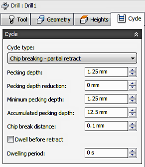
Cycle Type
The Cycle type is the type of drilling cycle. Inventor CAM provides a number of predefined (canned) drilling cycles.
Selecting a drill cycle determines which parameters can be specified for the drilling operation.
- Drilling - rapid out - Feed in to the programmed depth and rapid out. Used for Center Drilling, Spot Drilling and holes with depths of less than three times the tool diameter.
- Counterboring - dwell and rapid out - Feed in to the programmed depth, dwell for a specified time and rapid out. Used to create a flat bottom on shallow clearance for screws. The dwell improves the finish on the floor of the hole.
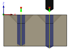
- Chip breaking - partial retract - For holes with depths of more than three or four times the tool diameter tool. Uses multiple pecks that periodically retracting the tool to break the chips and/or allow coolant to enter the hole. This is also known as Peck drilling.
- Deep drilling - full retract - Similar to Chip breaking, but retracts the tool completely out of the hole to clear chips and/or flood the hole with coolant. This is also known as Peck drilling.
- Break through - Allows for reduced feed and speed before breaking through a hole.
- Guided deep drilling - gun drilling - A standard gun drill has a single effective cutting edge. This unique head geometry is different from a conventional twist drill. While drilling, guide pads burnish the hole allowing the hole to maintain straightness. The result of this activity is a very round hole with a precision diameter that can also produce deep, straight holes in a variety of materials.
- Tapping - Tapping is a process that cuts threads into a hole, to accept screws. Taps right or left threads in a round hole with a multi-point tool that looks similar to a screw. This is used with self reversing tapping heads
- Left tapping - Creates a threaded hole for left handed screws. The tap rotates counterclockwise as it enters the hole and reversed to exit the hole.
- Right tapping - Creates a threaded hole for right handed screws. The tap rotates clockwise as it enters the hole and reversed to exit the hole.
- Tapping with chip breaking - Creates a threaded hole by feeding in and out multiple times, going deeper each time, until it reaches the final depth.
- Reaming - feed out - Feeds in and immediately feeds out after reaching the final depth. This is a precision hole finishing operation.
- Boring - dwell and feed out - Similar to Reaming, but includes a dwell at the bottom depth.
- Stop boring - stop and rapid out - Feeds in to the depth, stops the spindle rotation and rapids out. This does drag the boring insert along the wall during the retract.
- Fine boring - shift Similar to Stop Boring, except that it will orient the tip of the insert and move it away from the wall of the bore before performing the retract move.
- Back-boring - moves to a depth inside the hole and stops, while a reverse counterboring tool is attached. The spindle then starts and the tool feeds up, to counter bore the back side of the part.
- Circular pocket milling - This can be used to initiate a custom canned cycle on the control for circular pocketing.
- Bore milling - This can be used to initiate a custom canned cycle on the control for helical bor milling.
- Thread milling - This can be used to initiate a custom canned cycle on the control for thread milling.
- Probe - Used to measure a feature on the part with a probe tool, or use macros from the machine to define the WCS. Needs special handling in the post processors depending on the machine. See the more advanced Probing function, under the Setup pull down.
Pecking Depth
Sets the depth for the first peck move, which plunges in and out of the material to clear and break chips.
Pecking Depth Reduction
The amount by which the pecking depth is reduced per peck.
Minimum Pecking Depth
The minimum allowed pecking depth.
Accumulated Pecking Depth
Specifies the pecking depth which forces full retract.
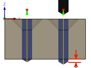
Chip Break Distance
With a chip breaking operation, the drill withdraws a specified distance after advancing into the hole to prevent the binding of chips.
Dwell Before Retract
Enables dwelling before pecking retracts to thin out chips. This can increase tool lift significantly depending on the material being machined.
Dwelling Period
The Dwelling period is the dwelling time in seconds. Specifying a dwell time halts all axis movement for a specified time while the spindle continues revolving at the specified rpm. This can be used to ensure that chips are cleared before retracting from a hole, and will typically improve the finish of a hole.
Typically a dwelling time between 1/4 second and 1 second is sufficient. As an example, specify 0.25 or 1/4 in this field to dwell for 1/4 second.
When post processing a drill cycle, the dwell time is specified as one of the drill cycle parameters (typically P), and in most cases it is output in milliseconds (ms).
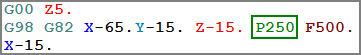
250ms dwell time in G82
When posting using expanded cycles, the dwell time is output as a regular dwell command (G4).
To calculate the minimum dwell time that will ensure at least one complete revolution, use a value of 60 divided by the spindle speed. As an example, at 350 RPM the minimum dwell time should be 60 / 350 = 0.171s (which could be rounded to 0.2s).