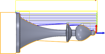
Profile is used for both roughing and finishing the part. Machine Outside Diameter (OD), Inside Diameter (ID) and Face profiles. You can control the cut direction, tool orientation and limit the toolpath area by using Geometry - Confinement boundaries.
 |
|
|
Access: |
Ribbon:
CAM tab
 Turning panel
Profile
Turning panel
Profile

|
 Tool tab settings
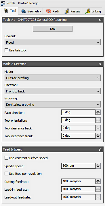
Tool
Select a turning tool from the library, or create a new turning tool.
Coolant
Select the type of coolant that should be used with the tool. Output options will vary depending on the machine capabilities and machine postprocessor configuration.
Use Tailstock
A tailstock can be used to support the open end of the workpiece. This is particularly useful when the workpiece is relatively long and slender, or large and heavy. Failing to use a tailstock can cause the workpiece to flex while being cut, causing poor surface finish (chatter) and inaccuracies.
For this option to take effect, your machine needs a programmable tailstock and your post processor has to be configured to write the code your specific machine needs. Once configured, the post will output the appropriate code to extend the tailstock forward at the beginning of the operation and retract the tailstock backward at the end of the operation.
Turning Mode
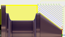
| Outside profiling
The tool approaches from/retracts to the outside of the stock and machines along the spindle axis (axially) depending on the Pass Direction setting (below). |
|
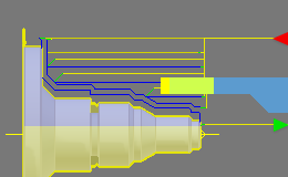
| Face profiling
The tool approaches from the front and machines radially. The cut can be outside to inside or inside to outside, depends on the Direction setting (below). |
|
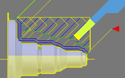
| Inside profiling
The tool approaches from/retracts to the centerline and machines axially depending on the Pass Direction setting (below). |
|
Direction
| Front to back
Select this option to cut from the front side of the stock, towards the back side, i.e. towards the main chuck. |
 |
| Back to front
Cuts from the back side, toward the front side. Away from the chuck. For tools with special geometry where chip thinning control is important. See the Use Back Cutting option shown on the Passes tab. |
 |
| Both ways
This option allows the tool to cut in both directions. The result is a back and forth cutting motion. Ensure that you are using a tool that can cut in both directions, when selecting this option. |
 |
Grooving (Undercuts)
Allows the tool to cut below the face of the part for undercut areas. If Disabled, the tool can only create cuts that move straight along the outer face of the stock. When Enabled, the tool can plunge into the stock in narrow areas to relieve undercuts. These are the options to control plunge direction.
| Dont Allow Groove.
With this setting the tool will not dip into any undercut areas of the part. |
|
| Allow Radial Grooving.
The tool will only plunge in areas that undercut the OD/ID of the part, without violating the model. |
|
| Allow Axial Grooving.
The tool will only plunge in areas that undercut any faces of the part, without violating the model. |
|
| Allow Radial and Axial Grooving.
The tool will plunge into any areas that undercut the part, without violating the model. |
|
| Allow Radial and Axial Grooving.
Same as above. Note the efficiencies of selecting the right tool. |
|
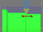
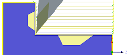
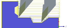
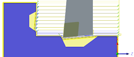
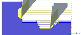
Pass Direction
Specifies the direction of the passes.
 |
 |
|
|
Pass direction @ 0 degrees |
Pass direction @ 30 degrees |
Pass direction matches part |
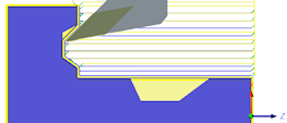
Tool Orientation
 |
|
|
Tool Orientation @ 45 degrees. |
Tool Orientation @ 90 degrees. |
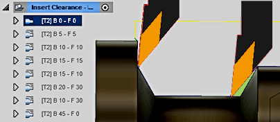
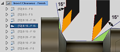
Tool Clearance - Back/Front
Specifies an additional tool clearance angle for the front and back edges of the insert. Sets the amount of relief between the part and the cutting tool. Allows for a more gradual entry into the part and exerts less pressure on the tool. Changing the Back Clearance will adjust the Front Clearance to the same amount. You can manually change the Front to a different value.
| Back = 0° and Front = 0° (No adjustment)
Clearance is not changed. The toolpath will feed in along the tools actual front & back clearance angle. |
|
| Back = 15° and Front = 15° (Equal adjustment)
Additional clearance for the back edge and the front edge are adjusted with an equal amount of clearance. |
|
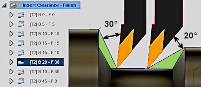
| Back = 20° and Front = 30° (Independent adjustment)
Additional clearance for the back edge and the front edge are adjusted with independent clearance amounts. |
|
Use Constant Surface Speed
Enable to automatically adjust the spindle speed to maintain a constant surface speed between the tool and the workpiece as the cutting diameter changes . Constant Surface Speed (CSS) is specified using G96 on most machines.
Surface Speed
The cutting speed expressed as the speed of the tool across the part surface. Expressed as Ft/min or M/min depending on the current Units setting.
Spindle Speed
The rotational speed of the spindle.
Maximum Spindle Speed
Specifies the maximum allowed spindle speed when using Constant Surface Speed (CSS).
Use Feed per Revolution
Enable to switch from Distance over Time (In/Min or MM/min), to Feed Per Revolution (IPR or MMPR). This type of feedrate creates a constant chip load regardless of the spindle RPM.
Cutting Feedrate
Feed used in cutting moves. Input based on the Use Feed per Revolution setting and the current Units.
Lead-In Feedrate
Feed used when leading in to a cutting move. Input based on the Use Feed per Revolution setting and the current Units.
Lead-Out Feedrate
Feed used when leading out from a cutting move. Input based on the Use Feed per Revolution setting and the current Units.
 Geometry tab settings
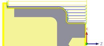
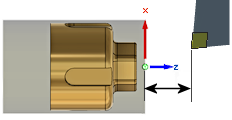
Front / Back Confinement
Used to limit the toolpath by Confining an area. Toolpaths can be contained within a specific region. Front/Back Confinement Mode lets you set the reference point for defining the containment area of the toolpath and Offset lets you adjust the boundary positive or negative from that reference. You can use these options to extend the toolpath past the model for a longer cut.

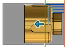
Front Confinement is show in Orange - Back Confinement is shown in Green.
Front / Back Mode
Specifies the reference position for the Front/Back Confinement boundary. These are the options for selecting the reference.
- Stock Front - Allows you to set the reference in relation to the Front of the Stock.
- Stock Back - Allows you to set the reference in relation to the Back of the Stock.
- Chuck Front - Allows you to set the reference in relation to the Chuck Face.
- Model Front - Allows you to set the reference in relation to the Front of the Model.
- Model Back - Allows you to set the reference in relation to the Back of the Model.
- Selected Point - Select a vertex or an edge for the origin reference.
- Origin - Allows you to set the reference in relation to the part Zero position.

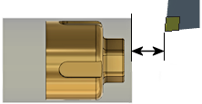
Chuck Front

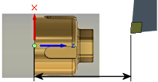
Offset
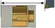
Specifies the distance to shift the machining boundary from the reference position shown above. You can specify a positive or negative distance from the reference point, or dynamically drag the position with your mouse. Front boundary is shown in Orange and Back boundary is shown in Green.
Front of Model Reference with .200" Offset
Selected Reference (blue edge) with -.250" Offset
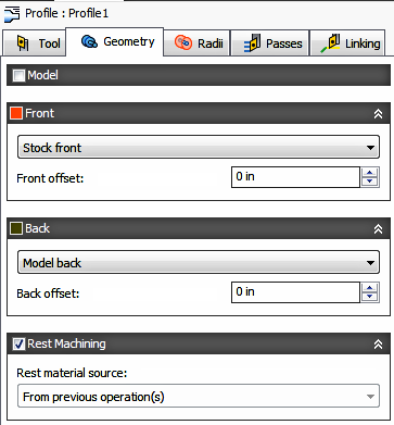
Rest Machining
Specifies that only stock left after previous operations should be machined.
Disabled The toolpath will clear out the entire area selected. |
Enabled The toolpath will only remove sections of the material that were not cleared out by the previous toolpath. |
Rest Material Source
Specifies the source from which the rest machining is to be calculated.
- From previous operation(s)
- From operation(s)
- From tool
- From file
- From solid(s)
- From setup stock
 Radii tab settings
|
|
|
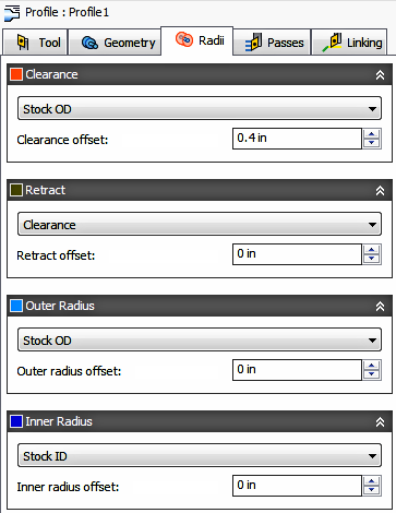
Radii Options for Outside Turning . |
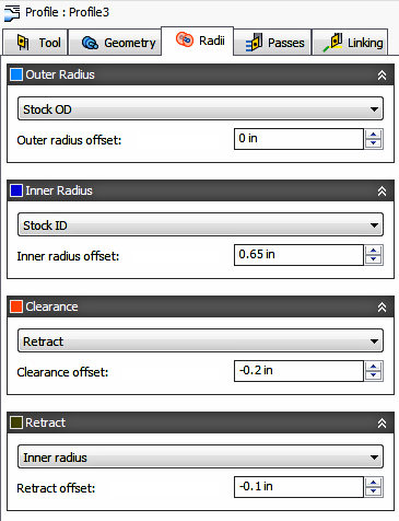
Radii Options for Inside Turning. |
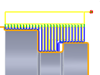
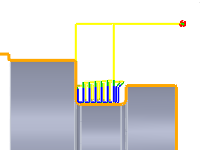
The Radii tab allows you to set a radial containment area for machining. The dialog will change depending on if the Turning Mode (Tool tab parameter) is set to Outside Profiling or Inside Profiling. These parameters are color coded for easy identification.

|

|
Order for Outside Turning. |
Order for Inside Turning. |
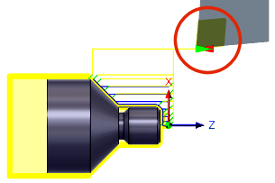
Clearance
Shown in Orange, this controls the radius where the tool rapids to at the start and end of the toolpath. For OD machining this position is outside the part. For ID machining this position is from an inside tube or bore. The tool approaches from and retracts to this position.
Shown in Orange, "From" sets the Clearance radius reference position. The reference can be in relation to the Stock, the Model, a specified Radius, Diameter, or any of the other Radial positions. This reference position can be shifted with a positive or negative offset value.
- Retract - Sets the Clearance radius in reference to the Retract Position.
- Stock OD- Sets the Clearance radius in reference to the outside diameter of the defined Stock.
- Model OD - Sets the Clearance radius in reference to the outside diameter of the defined Model.
- Outer radius - Sets the Clearance radius in reference to the Outer radius position. The Clearance radius must be larger than the Outer radius. Use the Offset parameter to make adjustments as needed.
- Inner radius - Sets the Clearance radius in reference to the Inner radius position. The Clearance radius must be larger than the Inner radius. Use the Offset parameter to make adjustments as needed.
- Model ID - Sets the Clearance radius in reference to the inside diameter of the Model, as defined in the Setup. Use the Offset parameter to make adjustments as needed.
- Stock ID - Sets the Clearance radius in reference to the inside diameter of the Stock, as defined in the Setup. Use the Offset parameter to make adjustments as needed.
- Selection - Select any face, vertex, or point on the model to define the Clearance radius. Use the Offset parameter to make positive or negative adjustments as needed..
- Radius - This option allows you to enter a radius value in the Offset field. This value is in reference to the centerline of the part and will not recognize any associative changes to the model.
- Diameter - This option allows you to enter a diameter value in the Offset field. This value is in reference to the centerline of the part and will not recognize any associative changes to the model.
Offset
Use this offset to shift the position relative to the Reference point selected above. You can make positive or negative adjustments as needed.
|
|
|
For Outside Turning. |
For Inside Turning. |
Retract
Shown in Dark Green, this controls the position above the surface you plan to machine. This is the radius where the tool retracts to between cuts.
Shown in Dark Green, "From" sets the Retract reference position. The reference can be in relation to the Stock, the Model, a specified Radius, Diameter, or any of the other Radial positions. This reference position can be shifted with a positive or negative offset value.
- Clearance - Sets the Retract radius in reference to the Clearance Position.
- Stock OD- Sets the Clearance radius in reference to the outside diameter of the defined Stock.
- Model OD - Sets the Clearance radius in reference to the outside diameter of the defined Model.
- Outer radius - Sets the Clearance radius in reference to the Outer radius position. The Clearance radius must be larger than the Outer radius. Use the Offset parameter to make adjustments as needed.
- Inner radius - Sets the Clearance radius in reference to the Inner radius position. The Clearance radius must be larger than the Inner radius. Use the Offset parameter to make adjustments as needed.
- Model ID - Sets the Clearance radius in reference to the inside diameter of the Model, as defined in the Setup. Use the Offset parameter to make adjustments as needed.
- Stock ID - Sets the Clearance radius in reference to the inside diameter of the Stock, as defined in the Setup. Use the Offset parameter to make adjustments as needed.
- Selection - Select any face, vertex, or point on the model to define the Clearance radius. Use the Offset parameter to make positive or negative adjustments as needed..
- Radius - This option allows you to enter a radius value in the Offset field. This value is in reference to the centerline of the part and will not recognize any associative changes to the model.
- Diameter - This option allows you to enter a diameter value in the Offset field. This value is in reference to the centerline of the part and will not recognize any associative changes to the model.
Offset
Same function as the Clearance Offset shown above.
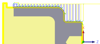
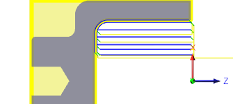
Outer Radius
Shown in Light Blue, this defines the largest radial boundary of the cutting area. For Outside (OD) machining, Outer Radius defines the outer stock surface you plan to machine. For Inside (ID) machining, Outer Radius controls the maximum depth for the cut area.

|

|
|
For Outside Turning. |
For Inside Turning. |
Shown in Light Blue, "From" sets the Outer Radius reference position. The reference can be in relation to the Stock, the Model, a specified Radius, Diameter, or any of the other Radial positions. This reference position can be shifted with a positive or negative offset value.
- Clearance - Sets the Retract radius in reference to the Clearance Position.
- Retract - Sets the Clearance radius in reference to the Retract Position.
- Stock OD- Sets the Clearance radius in reference to the outside diameter of the defined Stock.
- Model OD - Sets the Clearance radius in reference to the outside diameter of the defined Model.
- Inner radius - Sets the Clearance radius in reference to the Inner radius position. The Clearance radius must be larger than the Inner radius. Use the Offset parameter to make adjustments as needed.
- Model ID - Sets the Clearance radius in reference to the inside diameter of the Model, as defined in the Setup. Use the Offset parameter to make adjustments as needed.
- Stock ID - Sets the Clearance radius in reference to the inside diameter of the Stock, as defined in the Setup. Use the Offset parameter to make adjustments as needed.
- Selection - Select any face, vertex, or point on the model to define the Clearance radius. Use the Offset parameter to make positive or negative adjustments as needed..
- Radius - This option allows you to enter a radius value in the Offset field. This value is in reference to the centerline of the part and will not recognize any associative changes to the model.
- Diameter - This option allows you to enter a diameter value in the Offset field. This value is in reference to the centerline of the part and will not recognize any associative changes to the model.
Offset
Same function as the Clearance Offset shown above.
Inner Radius
Shown in Dark Blue, this defines the smallest radial boundary of the cutting area. For Outside (OD) machining, Inner Radius controls the maximum depth for the cut area . For Inside (ID) machining, Inner Radius defines the inner stock surface you plan to machine.
|
|
|
|
For Outside Turning. |
For Inside Turning. |
Shown in Dark Blue, "From" sets the Inner Radius reference position. The reference can be in relation to the Stock, the Model, a specified Radius, Diameter, or any of the other Radial positions. This reference position can be shifted with a positive or negative offset value.
Same as the Outer Radius "From" options shown above.
Offset
Same function as the Clearance Offset shown above.
 Passes tab settings
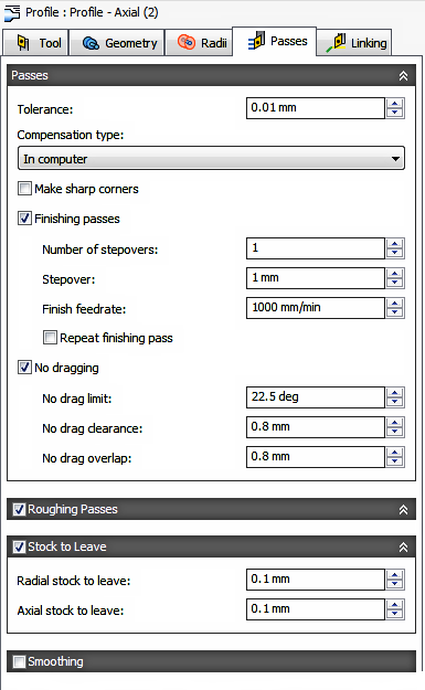
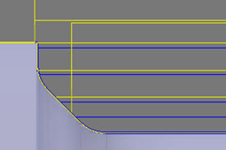
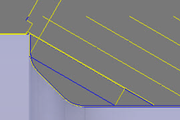
Tolerance
Also known as the Cut Tolerance, this Tolerance is for toolpath generation and geometry triangulation. Any additional filtering tolerances, like Smoothing, must be added to this tolerance to get the Total Tolerance for the cut..
 |
 |
|
Loose Tolerance .100 |
Tight Tolerance .001 |
CNC machine motion is controlled using G1 line and G2 G3 arc commands. To accommodate this Inventor CAM approximates spline and surface toolpaths by linearizing them; creating many short line segments to approximate the desired shape. How accurately the toolpath matches the desired shape depends largely on the number of lines used. More lines result in a toolpath that more closely approximates the nominal shape of the spline or surface.
Data Starving
A tighter tolerance will result in a more accurate path with smaller line segments. It is tempting to always use very tight tolerances, but there are trade-offs including longer toolpath calculation times, large G-code files and very short line moves. Each can be a problem depending on your situation. Inventor CAM will calculate quickly on almost any computer. But if you have an older NC control with limited memory and a machine with slower axis drives, the toolpath motion might appear jumpy. This is a phenomenon known as data starvation. This Tolerance, along with Smoothing, can reduce your program size and improve your machines performance.
Data starving occurs when the control becomes so overwhelmed with data that it cannot keep up. CNC controls can only process a finite number of lines of code (blocks) per second. That can be as few as 40 blocks/second on older machines and 1,000 blocks/second or more on a newer machines. Short line moves and high feedrates can force the processing rate beyond what the control can handle. When that happens, the machine must pause after each move and wait for the next servo command from the control.
Compensation Type
Specifies the compensation type.
- In computer - The toolpath position is calculated by Inventor CAM, based on the selected tool diameter. The postprocessed output contains the actual centerline position of the tool moving around the selected edge of the part.
- In control - The toolpath position is not calculated, but rather the actual coordinates of the part edge are output. Cutter Compensation codes (G41/G42) are output to the NC program. This allows the operator to enter the full diameter of the tool, into the controls Cutter Comp offset table, to compensation for the cutter position on the machine tool control.
- Wear - Works as if In computer was selected, but also outputs the Cutter Comp Left code. This lets the machine tool operator adjust for tool wear at the machine. by entering the difference in tool size from the programmed to, to the actual tool being used.
- Inverse wear - Identical to the Wear option, except that the Cutter Comp Right code is output.
Make Sharp Corners
When checked Inventor CAM will force sharp corners in the NC toolpath output. When unchecked (default) Inventor CAM will roll the tool around all sharp corners. This type of motion reduces cycle time, improves surface finish control and allows the machine to flow smoothly between faces.
Finishing Passes
Enable to perform finishing passes. If Roughing is disabled, the Turning Profile toolpath becomes a Finishing Only toolpath. With Roughing & Finishing both enabled, you can rough and finish part with 1 tool.

Both Rough & Finish Passes Enabled. |
Finish Pass Enabled. Rough Pass Disabled. |
Number of Stepovers
The number of finishing steps.
Stepover
Specifies the stepover distance between passes.
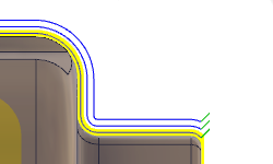
Multiple Finishing Stepovers
Repeat Finishing Pass
When checked this creates 1 additional finishing pass at 0.0 stock. This remove stock left due to tool deflection. Commonly referred to as a Spring Cut
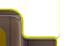
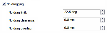
No Drag
When selected, moves that apply negative pressure on the insert are eliminated. Removes cuts up vertical walls and faces within the angle limit shown below. Before reaching the end of the cut, the tool retracts and changes position to cut down the wall
|

|
No Drag Limit
Specifies the angle limit that triggers the No Drag behavior. The angle is measured relative to the cutting edge of the tool.
No Drag Clearance and Overlap
No Drag Stop Clearance |
No Drag Overlap Distance |
Roughing Passes
Enable to perform roughing passes.
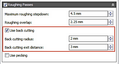
Maximum Roughing Stepdown
Specifies the maximum cut stepdowns for roughing.
Maximum Stepdown
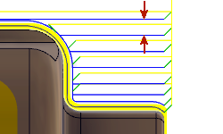
Roughing Overlap
Specifies the radial overlap of the roughing passes. A good overlap will insure the surface is smooth for finishing.
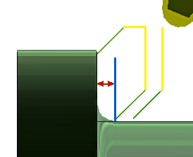
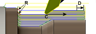
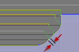
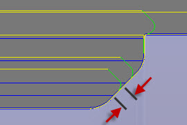
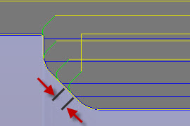
Use Back Cutting
For tools with special geometry where chip thinning control is important. This activates additional cutting controls. Only available when the cutting direction is set from Back to Front. See the Tool tab for Mode & Direction.
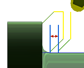
Starting the toolpath closest to the chuck side, the Radius (R) blends onto the cut and feeds in the positive direction (C). At a distance before the end of the cut (D), the feedrate is reduced to prevent chipping of the part or the tool.
Back Cutting Radius (R) - Consult your tooling supplier for their recommendation on the best Radius blend size. Generally a Radius equal to, or larger than the Maximum Roughing Stepdown will work as a starting point.
Back Cutting Exit Distance (D) Consult your tooling supplier for their recommendation on the best distance and feedrate to use. This uses the Lead-Out Feedrate shown on the Tools Tab.
|
|
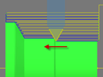
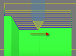
Use Pecking
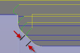
Use Pecking creates multiple steps across the length of the cutting direction. Between Pecking Depths the tool retracts along its path by the specified Pecking Retract distance. Use this if your material creates long strings of chips.
Pecking Depths - Specifies the step distance per Peck along the length of the cutting direction. The distance to feed along the cut, between retracts.
Pecking Retract - Specifies the Retract distance between Pecks along the cutting direction.
Tip: To see the points where the tool is pecking and retracting. Go to Simulation and under the Show Toolpath group, enable the Show points icon.

|
|
| Shown with an 18mm Peck (red arrow) and a 3mm Retract (green arrow) |
Stock to Leave
| Positive Stock to Leave
The amount of stock left after the operation is completed. This can be removed by subsequent roughing or finishing operations. It's common to leave a small amount of material after a roughing operation. |
 |
| No Stock to Leave
Remove all excess material up to the selected geometry. |
 |
| Negative Stock to Leave
Removes material beyond the part surface or boundary. |
 |
Radial (OD/ID) Stock to Leave - Axial (face) Stock to Leave
The Radial Stock to Leave parameter controls the amount of material to leave in the radial direction, i.e. Outside Diameter or Inside Diameter. Specifying a positive Radial stock to leave results in material being left on the OD or ID of the part.
The Axial Stock to Leave parameter controls the amount of material to leave in the axial direction (along the Z-axis), i.e. On the faces of flanges. Specifying a positive Axial stock to leave results in material being left on the Faces and shallow areas in the Z direction.
Changing the Radial stock amount automatically sets the Axial stock to the same value. You can manually enter a different Axial stock amount to leave. When using unequal amounts of stock, surfaces that are not exactly horizontal/vertical, Inventor CAM interpolates between the axial and radial stock amounts. So the stock left on these surfaces might be different from the specified value, depending on surface slope.

|

|
|
Axial stock to leave |
Radial stock to leave |
For finishing operations, it's common to set the default value to 0 mm / 0 in, i.e. no material is left.
For roughing operations, it's common to leave a small amount of material that can then be removed later by one or more finishing operations.
Negative stock to leave
When using a negative stock to leave, the machining operation removes more material from your stock than your model shape. This can be used to machine electrodes with a spark gap, where the size of the spark gap is equal to the negative stock to leave.
Both the radial and axial stock to leave can be negative numbers. However, the negative radial stock to leave must be less than the tool radius. When using a large nose radius or a button type insert with a negative stock, the negative stock must be less than or equal to the radius.
Smoothing
Smooths the toolpath by removing excessive points and fitting arcs where possible within the given filtering tolerance.
 |
 |
|
Smoothing Off |
Smoothing On |
Smoothing is used to reduce code size without sacrificing accuracy. Smoothing works by replacing collinear lines with one line and tangent arcs to replace multiple lines in curved areas.
The effects of smoothing can be dramatic. G-code file size may be reduced by as much as 50% or more. The machine will run faster and more smoothly and surface finish improves. The amount of code reduction depends on how well the toolpath lends itself to smoothing. Toolpaths like Parallel and Contour, that lay primarily in a major plane (XY, XZ, YZ), filter well. Those that do not, such as 3D Scallop, are reduced less.
Smoothing Tolerance
Specifies the smoothing filter tolerance. Different than the standard Tolerance (shown above), Smoothing Tolerance is how accurately the linearized points fit together.
If your part profile contains many splines, the spline curve is broken into small linear pieces. Smoothing fits those endpoints together, within the Smoothing Tolerance, to create a contour of blended arcs (G02/G03). Smoothing Tolerance and Tolerance should be combined, to understand the Total Tolerance of the toolpath being generated.
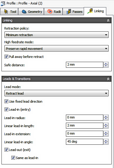
 Linking tab settings
|

|

|
Retraction Policy
Controls how the tool should retract to the clearance diameter after every cutting pass. or just retract a short distance away from the job. The distance is determined by the Safe Distance value.
 |
 |
| Full retraction - completely retracts the tool to the Retract Height at the end of the pass before moving above the start of the next pass. | Minimum retraction - moves straight up to the lowest height where the tool clears the workpiece, plus any specified safe distance. |
High Feedrate Mode
Specifies when rapid movements should be output as true rapids (G0) and when they should be output as high feedrate movements (G1).
- Preserve rapid movement - All rapid movements are preserved.
- Preserve axial and radial rapid movement - Rapid movements moving only horizontally (radial) or vertically (axial) are output as true rapids.
- Preserve axial rapid movement - Only rapid movements moving vertically.
- Preserve radial rapid movement - Only rapid movements moving horizontally.
- Preserve single axis rapid movement - Only rapid movements moving in one axis (X, Y or Z).
- Always use high feed - Outputs rapid movements as (high feed moves) G01 moves instead of rapid movements (G0).
This parameter is usually set to avoid collisions at rapids on machines which perform "dog-leg" movements at rapid.
High Feedrate
The feedrate to use for rapids movements output as G1 instead of G0.
Pull Away Before Retract
Enable to move away from the stock before retracting when possible. By disabling this option, retracts will touch the stock.
Safe Distance
Minimum distance between the tool and the part surfaces during retract moves. The distance is measured after stock to leave has been applied, so if a negative stock to leave is used, special care should be taken to ensure that safe distance is large enough to prevent any collisions.
Approach and Retract
Used to define how the tool should position at the start of the operation and the end of the operation. The default position is in reference to the Safe Z as defined in the Setup. You can override the Setup Safe Z position with the options shown below.
- Safe Z - The Approach position will be the same as the Safe Z position defined in the Setup.
- First Toolpath Position - The Approach position will be the same as the first Z position of the toolpath.
Approach Z - Defines how the tool will position before the start of the toolpath.
- Safe Z - The Approach position will be the same as the Safe Z position defined in the Setup.
- Last Toolpath Position - The Retract position will be the same as the Last Z position of the toolpath.
Retract Z - Defines how the tool will position after completing the toolpath.
Override Setup Safe Z
Enable to redefine the Reference position for the Safe Z retract.
- Setup WCS Origin - Set reference to the Work Coordinate Offset position set in the Setup
- Stock Front - Set the reference to the Stock Font position
- Stock Back - Set the reference to the Stock Back position
Safe Z Reference - Select the new reference position to set the Safe Z retract.
Safe Z Offset
Set the distance to shift from the reference position specified above.
WCS Reference and Offset Distance |
WCS Reference and Offset Distance |
Stock Front Reference and Offset Distance |
Stock Back Reference and Offset Distance |
Lead Mode
The lead mode settings provide very specific control of the leads. There are five options available.
- Fail - Results in a failure if it is not possible to do the lead in/outs without causing a gouge. User intervention is then required to make the leads fit.
- Discard passes - Discards any passes that cannot be reached with the given settings. This option leaves rest material for any following operations.
- Move lead - Moves the lead position to a different location along the part until there is room, but keeps the lead as specified.
- Turn lead - Changes the lead angle until there is room.
- Retract lead - Is the most automatic lead mode and also the default setting. It allows linking of all parts and, in some cases, does radial retracts when there is no other alternative. This is the recommended setting.
Use Fixed Lead Direction
Specifies that the given lead directions are always relative to the XZ coordinate system. When disabled, the leads are relative to the front/back cutting direction of the individual pass.
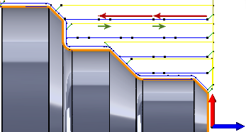
Lead-In (Entry)
Enable to generate a lead-in (red arrow) move onto the cut profile.
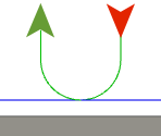
Lead-in (red arrow)
Lead-In Radius
Specifies the radius of the lead-in move at the start of a cutting pass.
 |

|
|
Lead-In Radius @ 0mm |
Lead-In Radius @ 3mm |
Linear Lead-In Length
Specifies the distance (length) of the lead-in move at the start of a cutting pass.
 Linear Lead-In Distance set to 1mm |
 Linear Lead-In Distance set to 5mm |
Lead-In Extension
Specifies the lead-in extension value which has the effect of leading in before the point at which the cutting movement starts by the specified distance.
 Lead-In Extension set to 0mm |
 Lead-In Extension set to 1mm |
Linear Lead-In Angle
Specifies the angle of the lead-in move at the start of a cutting pass. Note that the angle reference depends on the Use Fixed Lead direction.
 Lead-In Angle @ 45 degrees |
 Lead-In Angle @ 90 degrees |
Lead-Out (Exit)
Enable to generate a lead-out (green arrow) move off of the cut profile.
Lead-out (green arrow)
Same as Lead-In
Specifies that the lead-out definition should be identical to the lead-in definition.
Linear Lead-Out Distance
Specifies the distance (length) of the lead-out move at the end of a cutting pass.
 Linear Lead-Out Distance set to 1 mm |
 Linear Lead-Out Distance set to 5 mm |
Lead-Out Extension
This setting has the effect of delaying the point at which the cutter begins to lead out by the specified distance.
 |
|
|
Lead-Out Extension set to 0mm |
Lead-Out Extension set to 1mm |
Lead-Out Radius
Specifies the radius of the lead-out move at the end of a cutting pass.
 |

|
|
Lead-Out Radius @ 0mm |
Lead-Out Radius @ 3mm |
Linear Lead-Out Angle
Specifies the angle of the lead-out move at the end of a cutting pass. Note that the angle reference depends on the Use Fixed Lead direction.
 Lead-Out Angle @ 45 degrees |
 Lead-Out Angle @ 90 degrees |