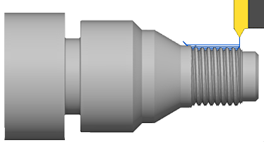
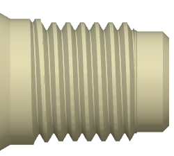
The Thread strategy is used for turning OD, ID, cylindrical and conical threads. The CNC control must have built-in support for synchronizing the spindle and feed.
|
Access: |
Ribbon:
CAM tab
 Turning panel
Thread
Turning panel
Thread

|
 Tool tab settings
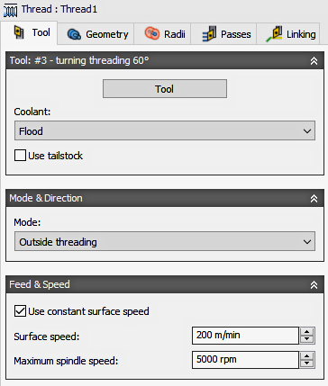
Coolant
Select the type of coolant that should be used with the tool. Output options will vary depending on the machine capabilities and machine postprocessor configuration.
Use Tailstock
A tailstock can be used to support the open end of the workpiece. This is particularly useful when the workpiece is relatively long and slender, or large and heavy. Failing to use a tailstock can cause the workpiece to flex while being cut, causing poor surface finish (chatter) and inaccuracies.
For this option to take effect, your machine needs a programmable tailstock and your post processor has to be configured to write the code your specific machine needs. Once configured, the post will output the appropriate code to extend the tailstock forward at the beginning of the operation and retract the tailstock backward at the end of the operation.
Turning Mode
| Outside Threading
The tool approaches from/retracts to the outside of the stock and machines along the spindle axis (axially). |
|
| Inside Threading
The tool approaches from/retracts to the centerline and machines axially. |
|
Use constant surface speed
Enable to automatically adjust the spindle speed to maintain a constant surface speed between the tool and the workpiece as the cutting diameter changes . Constant Surface Speed (CSS) is specified using G96 on most machines.
Surface Speed
The cutting speed expressed as the speed of the tool across the part surface. Expressed as Ft/min or M/min depending on the current Units setting.
Spindle Speed
The rotational speed of the spindle.
Maximum Spindle Speed
Specifies the maximum allowed spindle speed when using Constant Surface Speed (CSS).
Use Feed per Revolution
Enable to switch from Distance over Time (In/Min or MM/min), to Feed Per Revolution (IPR or MMPR). This type of feedrate creates a constant chip load regardless of the spindle RPM.
Cutting Feedrate
Feed used in cutting moves. Input based on the Use Feed per Revolution setting and the current Units.
Lead-In Feedrate
Feed used when leading in to a cutting move. Input based on the Use Feed per Revolution setting and the current Units.
Lead-Out Feedrate
Feed used when leading out from a cutting move. Input based on the Use Feed per Revolution setting and the current Units.
 Geometry tab settings
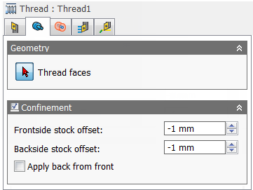
Thread Faces
Selection button for faces to be threaded.
Confinement
Toolpaths can be contained within a specific region using the Confinement button to select confinement boundaries. Confinement regions can be defined with a combination of edges, surfaces, or sketch points.
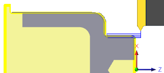
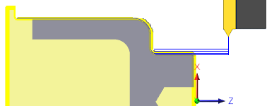
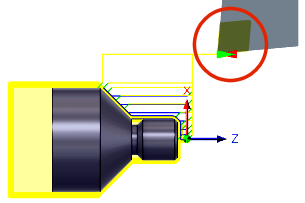
Frontside Stock Offset
Specifies the distance to machine beyond the frontside of the model. Positive lengthens the starting position. Negative shortens the starting position and can actually start further into the part.
| Zero Frontside Offset
Starts the toolpathat the edge of the stock. |
|
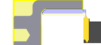
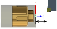
| Positive Frontside Offset
Starts the toolpath further away from the cutting area. |
|
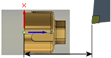
Backside Stock Offset
Specifies the distance to machine beyond the backside of the model. Positive lengthens the position at the end of the cut. Negative shortens the total threading distance, at the end of the cut.
| Zero Backside Offset
Ends the toolpath at the end of the cutting area. |
|
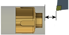
| Negative Backside Offset
Ends the toolpath to shorten the cutting area. |

|
Apply Back From Front
Makes the stock backside offset apply from the front side.
 Radii tab settings
The Radii tab allows you to set a radial containment area for machining. These parameters are color coded for easy identification.

|
Order for Radii Containment. |
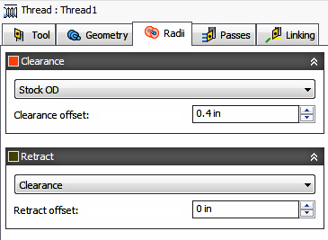
Clearance
Shown in Orange, this controls the radius where the tool rapids to at the start and end of the toolpath. The tool approaches from and retracts to this position.
Shown in Orange, "From" sets the Clearance radius reference position. The reference can be in relation to the Stock, the Model, a specified Radius, Diameter, or any of the other Radial positions. This reference position can be shifted with a positive or negative offset value.
- Retract - Sets the Clearance radius in reference to the Retract Position.
- Stock OD- Sets the Clearance radius in reference to the outside diameter of the defined Stock.
- Model OD - Sets the Clearance radius in reference to the outside diameter of the defined Model.
- Outer radius - Sets the Clearance radius in reference to the Outer radius position. The Clearance radius must be larger than the Outer radius. Use the Offset parameter to make adjustments as needed.
- Inner radius - Sets the Clearance radius in reference to the Inner radius position. The Clearance radius must be larger than the Inner radius. Use the Offset parameter to make adjustments as needed.
- Model ID - Sets the Clearance radius in reference to the inside diameter of the Model, as defined in the Setup. Use the Offset parameter to make adjustments as needed.
- Stock ID - Sets the Clearance radius in reference to the inside diameter of the Stock, as defined in the Setup. Use the Offset parameter to make adjustments as needed.
- Selection - Select any face, vertex, or point on the model to define the Clearance radius. Use the Offset parameter to make positive or negative adjustments as needed..
- Radius - This option allows you to enter a radius value in the Offset field. This value is in reference to the centerline of the part and will not recognize any associative changes to the model.
- Diameter - This option allows you to enter a diameter value in the Offset field. This value is in reference to the centerline of the part and will not recognize any associative changes to the model.
Offset
Use this offset to shift the position relative to the Reference point selected above. You can make positive or negative adjustments as needed.
|
|
In This Example... |
Retract
Shown in Dark Green, this controls the position above the surface you plan to machine. This is the radius where the tool retracts to between cuts.
Shown in Dark Green, "From" sets the Retract reference position. The reference can be in relation to the Stock, the Model, a specified Radius, Diameter, or any of the other Radial positions. This reference position can be shifted with a positive or negative offset value.
- Clearance - Sets the Retract radius in reference to the Clearance Position.
- Stock OD- Sets the Clearance radius in reference to the outside diameter of the defined Stock.
- Model OD - Sets the Clearance radius in reference to the outside diameter of the defined Model.
- Outer radius - Sets the Clearance radius in reference to the Outer radius position. The Clearance radius must be larger than the Outer radius. Use the Offset parameter to make adjustments as needed.
- Inner radius - Sets the Clearance radius in reference to the Inner radius position. The Clearance radius must be larger than the Inner radius. Use the Offset parameter to make adjustments as needed.
- Model ID - Sets the Clearance radius in reference to the inside diameter of the Model, as defined in the Setup. Use the Offset parameter to make adjustments as needed.
- Stock ID - Sets the Clearance radius in reference to the inside diameter of the Stock, as defined in the Setup. Use the Offset parameter to make adjustments as needed.
- Selection - Select any face, vertex, or point on the model to define the Clearance radius. Use the Offset parameter to make positive or negative adjustments as needed..
- Radius - This option allows you to enter a radius value in the Offset field. This value is in reference to the centerline of the part and will not recognize any associative changes to the model.
- Diameter - This option allows you to enter a diameter value in the Offset field. This value is in reference to the centerline of the part and will not recognize any associative changes to the model.
Offset
Same function as the Clearance Offset shown above.
 Passes tab settings
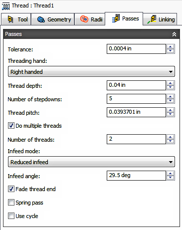
Tolerance
Also known as the Cut Tolerance, this Tolerance is for toolpath generation and geometry triangulation. Any additional filtering tolerances, like Smoothing, must be added to this tolerance to get the Total Tolerance for the cut..
 |
 |
|
Loose Tolerance .100 |
Tight Tolerance .001 |
CNC machine motion is controlled using G1 line and G2 G3 arc commands. To accommodate this, Inventor CAM approximates spline and surface toolpaths by linearizing them; creating many short line segments to approximate the desired shape. How accurately the toolpath matches the desired shape depends largely on the number of lines used. More lines result in a toolpath that more closely approximates the nominal shape of the spline or surface.
Data Starving
A tighter tolerance will result in a more accurate path with smaller line segments. It is tempting to always use very tight tolerances, but there are trade-offs including longer toolpath calculation times, large G-code files and very short line moves. Each can be a problem depending on your situation. Inventor CAM will calculate quickly on almost any computer. But if you have an older NC control with limited memory and a machine with slower axis drives, the toolpath motion might appear jumpy. This is a phenomenon known as data starvation. This Tolerance, along with Smoothing, can reduce your program size and improve your machines performance.
Data starving occurs when the control becomes so overwhelmed with data that it cannot keep up. CNC controls can only process a finite number of lines of code (blocks) per second. That can be as few as 40 blocks/second on older machines and 1,000 blocks/second or more on a newer machines. Short line moves and high feedrates can force the processing rate beyond what the control can handle. When that happens, the machine must pause after each move and wait for the next servo command from the control.
Threading Hand
|

|
|
Right Handed Threads |
Left Handed Threads |
Thread Depth
Specifies the thread depth. Shown below as "T", the thread depth is the Major Dia. - Minor Dia. / 2. ( T = D - d ÷ 2 )
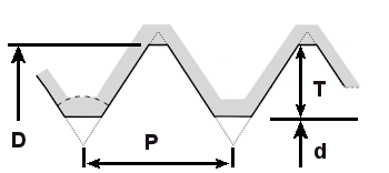
"D" = Major Dia. - "d" = Minor Dia. - "P" = Thread Pitch - "T" = Thread Depth
Number of Stepdowns
Specifies the number of cuts to complete the full thread depth.
Thread Pitch
Specifies the thread pitch. The Pitch is the distance of 1 thread. For inch threads it's 1 ÷ the number of threads per inch (TPI). A 1/2-13 thread the pitch would be 1÷13 = .0769. For metric threads the pitch is as stated. For an M16 x 2, the thread pitch is 2mm .
Do Multiple Threads
Enable to activate multiple lead threads.
Number of Threads
Specifies the number of thread leads.
Infeed Mode
The infeed is the depth of cut per pass and is critical in threading. The Infeed Mode is used to define how the tool should feed into the part. Each pass engages a larger portion of the cutting edge of the insert. There are three infeed mode options.
| Constant infeed - With this option, the cutting force and metal removal rate can increase dramatically from one pass to the next. Example: When producing a 60 degree thread form using a constant 0.010 inch infeed per pass, the second pass removes three times the amount of metal as the first pass. The amount of metal removed continues to grow exponentially with each subsequent pass. | 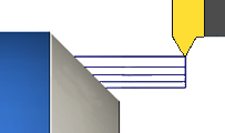
|
| Reduced infeed - This option maintains more realistic cutting forces and reduces the depth of cut with each pass. It avoids the increased metal removal rate of constant infeed. Normally set to 1/2 the insert angle, or slightly less ( 60° ÷ 2 - .5° = 29.5°). This it is the recommended setting. | 
|
| Alternate Flanking - This option is similar to Reduced infeed, but alternates the in-feed motion from side to side for each subsequent depth cut. | 
|
Infeed Angle
Specifies the infeed angle. Normally set to 1/2 the insert angle, or slightly less ( 60° ÷ 2 - .5° = 29.5°). This it is the recommended setting.
Fade Thread End
Enable to lift the thread off of the part gradually, just before reaching the end of the cut.
Spring Pass
Enable to perform the final finishing pass twice to remove stock left due to tool deflection. Also referred to as a spring cut.
Use Cycle
Enable to force the postprocessor to output the threading as canned cycle. May requires postprocessor modifications.
Number of Stepdowns
Specifies the desired number of increments to step down, to achieve the final depth.
 Linking tab settings
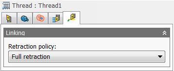

Retraction Policy
Controls how the tool should retract to the clearance diameter after every cutting pass. or just retract a short distance away from the job. The distance is determined by the Safe Distance value.
 |
 |
| Full retraction - completely retracts the tool to the Retract Height at the end of the pass before moving above the start of the next pass. | Minimum retraction - moves straight up to the lowest height where the tool clears the workpiece, plus any specified safe distance. |
Approach and Retract
Used to define how the tool should position at the start of the operation and the end of the operation. The default position is in reference to the Safe Z as defined in the Setup. You can override the Setup Safe Z position with the options shown below.
- Safe Z - The Approach position will be the same as the Safe Z position defined in the Setup.
- First Toolpath Position - The Approach position will be the same as the first Z position of the toolpath.
Approach Z - Defines how the tool will position before the start of the toolpath.
- Safe Z - The Approach position will be the same as the Safe Z position defined in the Setup.
- Last Toolpath Position - The Retract position will be the same as the Last Z position of the toolpath.
Retract Z - Defines how the tool will position after completing the toolpath.
Override Setup Safe Z
Enable to redefine the Reference position for the Safe Z retract.
- Setup WCS Origin - Set reference to the Work Coordinate Offset position set in the Setup
- Stock Front - Set the reference to the Stock Font position
- Stock Back - Set the reference to the Stock Back position
Safe Z Reference - Select the new reference position to set the Safe Z retract.
Safe Z Offset
Set the distance to shift from the reference position specified above.
WCS Reference and Offset Distance |
WCS Reference and Offset Distance |
Stock Front Reference and Offset Distance |
Stock Back Reference and Offset Distance |