The first and most important step for your CNC programming project. Define the face to machine, pick the zero position and set the stock size.
Creating a properly defined Setup, is an important first step for successful toolpath programming. Setup helps you set basic working conditions for CNC programming. The parameters will change depending on the Machine/Operation Type you select. Watch and read the ToolTips for each parameter.
- Select the Operation Type for the kind of machines you will be programming. Milling, Turning or Cutting
- Set the Orientation of the axes by picking a face or edge
- Select the Origin of the axes. The point where Zero should be located
- If your project has more than one model, select the model/models to consider for machining
- If your project contains fixtures, select the models that represent fixture components
- Define the Stock size and shape
- Add a program name and comment
- Set the Work Offset to use on the machine
Steps for defining the Job Setup.
|
Access: |
Ribbon:
CAM tab
 Job panel
 Setup
Setup

|
 Setup tab
Operation Type
Select the Operation Type for the kind of machines you will be programming. Milling, Turning or Cutting. Turning including lathes with live tooling and mill/turn configurations. Cutting is used for machines without rotary spindles, like Waterjet, Plasma and Laser cutting machines.

|
Milling - 2, 3, 4, 5 axis. 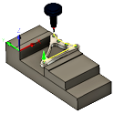
|
Turning - 2, 3, 4, 5 axis. 
|
Cutting - 2 axis. 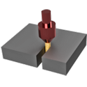
|

Spindle
If Turning or Mill/Turn is selected additional parameters will activate for selecting the active spindle.
- Primary spindle
- Secondary spindle
Radial Dimension Mode
Specifies if center line cylinder dimensions are shown as Radius or Diameter.
Continue Machining from Previous Setup
Specifies that the machining continues from the previous setup.
Work Coordinate System (WCS) - Milling and Cutting
The Work Coordinate System (WCS) is used to define the machining plane and the part zero origin. Coordinates in the postprocessed NC code will be referenced from this coordinate system. The WCS defaults to the Model orientation.
When selecting a machining plane the Z positive should point away from the face to be machined. The colored axis triad arrows indicate the positive direction for the axis. If no axis letter is shown Red represents X+, Green represents Y+ and Blue represents Z+.
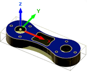
The Z axis points away from the face to be machined. |
 |
Orientation:
The Orientation: drop-down menu provides the following options to define the setup orientation of the X, Y, and Z WCS axes:
- Model orientation - Uses the orientation of the current part, as modeled, for the WCS orientation.
- Select Z axis/plane & X axis - Select a face or an edge to define the Z axis and another face or edge to define the X axis.
-
Select Z axis/plane & Y axis - Select a face or an edge to define the Z axis and another face or edge to define the Y axis.
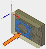
Face perpendicular to Z
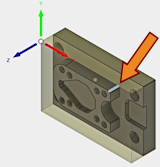
Edge aligned to Z
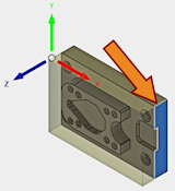
Face perpendicular to X

Edge aligned to X
-
Select X & Y axes - Select a face or an edge to define the X axis and another face or edge to define the Y axis. Use the same selection techniques as shown above.

Face perpendicular to Z

Edge aligned to Z
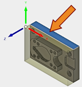
Face perpendicular to Y

Edge aligned to Y
- Select coordinate system - Sets the WCS orientation for the setup from an Inventor User Coordinate System (UCS) in the model. This uses both the origin and orientation of the existing coordinate system. Use this option if your model does not contain a suitable point and plane for your operation.
Flip Z and Flip X axis
If the axis is pointing in the wrong direction, you can use the Flip checkbox to change the positive reference 180°.
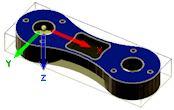
The Z axis points in the wrong direction. |

The Z axis Flipped 180°. |
Origin:
The Origin: defines the reference for the toolpaths. Coordinates in the postprocessed NC code will be referenced from this coordinate system. Select the Reference from the drop-down menu for locating the WCS origin.
- Model origin - Uses the coordinate system (WCS) origin of the current part for the WCS origin.
- Selected point - Select a vertex or an edge for the WCS origin.
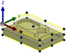
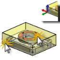
- Stock box point - Select a point on the stock bounding box for the WCS origin (image below).
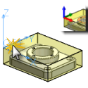
- Model box point - Select a point on the model bounding box for the WCS origin (image below).
|
 |
 |
There is also an Origin mini-toolbar that floats on the graphics area of the screen when Setup is invoked. It offers an alternative to the dialog box for WCS Origin selection.
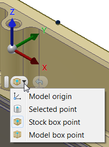
To reselect the Origin select the Undo button to the right of the pull down and pick a new Origin reference.
Stock Point
Specifies the stock point of the tool view.
Work Coordinate System (WCS) - Turning or Mill/Turn
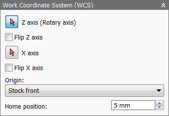
WCS options for a turning or mill/turn operation
- Z Axis (Rotary Axis) - Select any circular edge or cylindrical face to set the Z axis orientation.
- Z should point thru the center line of the part. Normally Z+ should point away from the chuck on the primary spindle
-
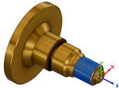
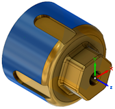
- Flip Z Axis - Flips the Z axis 180 degrees. Z+ should point away from the chuck on most machines.
-
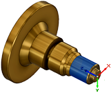

- X Axis - Specifies the X axis orientation of the part. Simple 2 axis turned parts may not need adjustment. For parts that require live tooling operations, you can use this to set the X reference position.
-

No X adjustment.
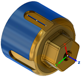
X is set to the line.
- Flip X Axis - Flips the X axis 180 degrees.
-

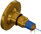
- Origin - You may choose the Stock front, Stock back, Model front, or Model back as the part origin.
- Home Position - Enter a value to specify the home position along the Z axis.
Safe Z - Turning or Mill/Turn
Sets the Z retract position between Turning toolpath operations. Select the reference point from the pull down menu and set the offset distance for the Z retract. This is a global Z retract position for all toolpaths. You can override this position within the Turning Toolpath on the Linking parameters tab.
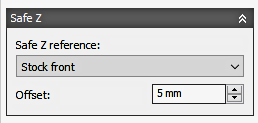
|
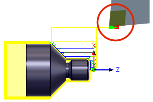
|
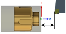
WCS Reference and Offset Distance |
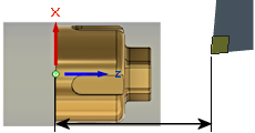
WCS Reference and Offset Distance |
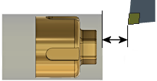
Stock Front Reference and Offset Distance |
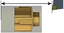
Stock Back Reference and Offset Distance |
Model
If your project only contains one model, no selection is required. All toolpaths will be applied to the visible model. If the project contains multiple models, select the model/models to be machined.
 Milling/Cutting Model selection |
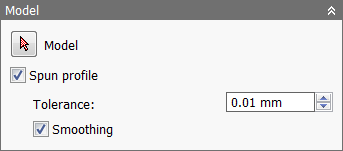 Turning Model selection |
Turning Model Options
- Spun Profile - Parts that require Mill/Turn toolpaths may have holes, slots or under cuts that can affect the Turning operations. Turned parts need to see the extents of the outer profile. Spun Profile creates a 2D sketch profile that is used for calculating the Turning toolpaths.
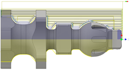
Spun Profile Off
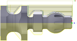
Spun Profile On
- Spun Profile Tolerance - Specifies the tolerance for the spun profile generation.
- Spun Profile Smoothing - Enable to smooth the profile.
Fixture
Vises, clamps and chucks are all examples of Fixture components. These are usually included in the project for visual reference, but Inventor CAM can check the toolpath against the location of these models to avoid collisions.
Select any fixtures that should be included for collision detection when verifying toolpaths during stock simulation.

 Stock tab settings
Inventor CAM toolpaths are calculated based on the available stock to remove. Defining the stock accurately is important. The stock you define and fixture components you select are used when simulating the toolpath.
| Rectangular Stock | Cylindrical Stock | Tubular Stock |
|

|

|

|
|

|
|
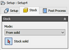
Solid Stock This is useful for parts that are cast or pre-machined. |
Mode:
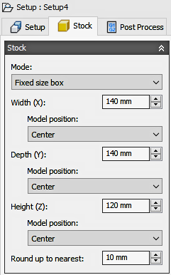
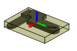 Fixed size box - Creates a cubic stock body that is of a specified (fixed) size. This is the default setting. Relative size box - Creates a cubic stock body that is larger than the model by given offset values, rounded up to the nearest specified increment. |
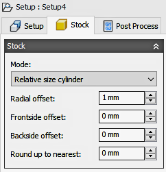
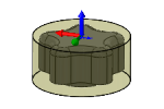 Fixed size cylinder - Creates a cylindrical stock body that is of a specified (fixed) size. This is the default setting. Relative size cylinder - Creates a cylindrical stock body that is larger than the model by given offset values, rounded up to the nearest specified increment. |
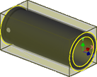
Fixed size tube - Creates a tube stock body that is of a specified (fixed) size. This is the default setting. Relative size tube - Creates a tube stock body that is larger than the model by given offset values, rounded up to the nearest specified increment. |
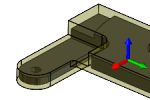 From Solid - Gives complete control over stock definition by using a solid body in a multi-body part, or from a part file in an assembly. |
Fixed Size Box Mode
- Width (X): - Enter a value to specify the stock width.
- Model position: Offset from left side (-X) - Specifies the offset of the stock in the negative X direction.
- Model position: Center - The model is centered along the X axis within the stock.
- Model position: Offset from right side (+X) - Specifies the offset of the stock in the positive X direction.
- Depth (Y): - Enter a value to specify the stock depth.
- Model position: Offset from back side (+Y) - Specifies the offset of the stock in the positive Y direction.
- Model position: Center - The model is centered along the Y axis within the stock.
- Model position: Offset from front side (-Y) - Specifies the offset of the stock in the negative Y direction.
- Height (Z): - Enter a value to specify the stock height.
- Model position: Offset from top (+Z) - Specifies the offset of the stock in the positive Z direction.
- Model position: Center - The model is centered along the Z axis within the stock.
- Model position: Offset from bottom (-Z) - Specifies the offset of the stock in the negative Z direction.
- Round up to nearest: - Specifies the rounding increment for the stock size.
Relative Size Box Mode
Relative size box mode provides options to add stock to the top, bottom, and/or sides of the stock.
 No additional stock |
 Sides and top-bottom |
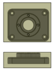 Add stock to all sides |
Fixed Size Cylinder Mode
- Axis - Specifies the axis of the cylindrical stock. Permissible selections include arcs, edges, and faces.
- Diameter: - Specifies the diameter of the stock.
- Length: - Specifies the length of the stock.
- Offset from front: - Positions the stock such that it is flush with the front face of the model.
- Center - Centers the model within the cylindrical stock.
- Offset from back - Positions the stock such that it is flush with the back face of the model.
- Round up to nearest: - Specifies the rounding increment for the stock size.
Relative Size Cylinder Mode
Like the Fixed size cylinder mode, the Relative size cylinder mode also lets you specify the axis of the cylindrical stock. In addition, you can specify radial, frontside, and backside offset values to better position your model relative to the stock.
- Axis - Specifies the axis of the cylindrical stock. Permissible selections include arcs, edges, and faces.
- Radial offset: - Specifies the radial offset of the stock.
- Frontside offset: - Specifies the distance to machine beyond the frontside of the model.
- Backside offset: - Specifies the distance to machine beyond the backside of the model.
- Round up to nearest: - Specifies the rounding increment for the stock size.
Fixed Size Tube Mode
- Axis - Specifies the axis of the tube stock. Permissible selections include arcs, edges, and faces.
- Diameter: - Specifies the outer diameter of the tube stock.
- Inner Diameter: - Specifies the inner diameter of the tube stock.
- Length: - Specifies the length of the stock.
- Offset from front: - Positions the stock such that it is flush with the front face of the model.
- Center - Centers the model within the tube stock.
- Offset from back - Positions the stock such that it is flush with the back face of the model.
- Round up to nearest: - Specifies the rounding increment for the stock size.
Relative Size Tube Mode
Like the Fixed size tube mode, the Relative size tube mode also lets you specify the axis of the tube stock. In addition, you can specify radial, frontside, and backside offset values to better position your model relative to the stock.
- Axis - Specifies the axis of the tube stock. Permissible selections include arcs, edges, and faces.
- Radial offset: - Specifies the radial offset of the stock.
- Frontside offset: - Specifies the distance to machine beyond the frontside of the model.
- Backside offset: - Specifies the distance to machine beyond the backside of the model.
- Round up to nearest: - Specifies the rounding increment for the stock size.
 Post Process tab settings

Post processing parameters like the program name or number, program comment, and work offset can be provided on the Post Process tab
The work offset is mapped by the post processor configuration to the corresponding zero table index (e.g. G54-G59) on the CNC control. A value of 1 would normally be setup to be the first available zero index on the CNC control (e.g. G54). The WCS and work offset are generally setup to match one another on a one-to-one basis.
Program name/number
Specifies the program name or number. This parameter is passed to the post processor.
Program comment
Specifies the program comment. This parameter is passed to the post processor.
WCS offset:
Identifies the desired workpiece coordinate system fixture offset (WCS) for the setup. 1 represents the first available fixture offset of the CNC control (On a Fanuc/Fadal control this would be a G54). The post processor maps this number to the actual WCS format for your machine.
Multiple WCS offsets
Enable this check box to specify that the workpiece is to be duplicated.
WCS offset duplicates:
Specifies the number of workpiece duplicates. This is the total number of instances.
WCS offset increment:
Specifies the work offset increment used for workpiece duplication.
Operation order:
Specifies the ordering of the individual operations.
- Preserve order - Specifies that features are machined in the order in which they were selected.
- Order by operation - Specifies the ordering of the individual operations.
- Order by tool - Specifies the ordering of operations by tool. For example, all operations that use a Ø3/4" flat mill are machined first. Then the next set of operations that use another identical tool, a Ø1/4" flat mill for example, are machined next.
Using Multiple Setup Work Offsets
Inventor CAM supports patterning of entire setups using the Multiple WCS offsets feature, which essentially duplicates entire setups using different work offsets. This feature is generally used when the individual position of each instance is not precisely known.
Once you enable Multiple WCS offsets, you can specify the total number of instances and the work offset increment to be used. You can also choose the order of the duplicated toolpath (by setup, by operation, or by tool).
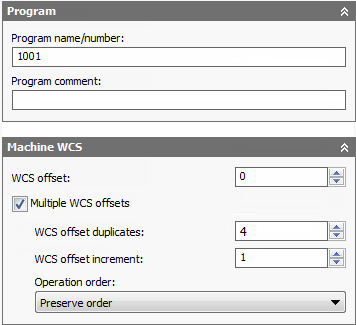
Enabling multiple work offsets
The setting for the WCS offset: field depends on the post processor. In this case we are using a Fanuc post, so specifying 1 will use the first work offset (G54). The next field is the number of duplications, in this case 4, so each of the next offsets is incremented by 1 and will then be G55, G56 and G57.
If the physical setups of each instance are evenly spaced, it is sometimes possible to use a normal pattern feature instead. This allows you to fully simulate the duplicated toolpath. However, this approach requires you to add toolpaths to align the stock for each instance.