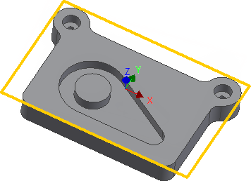
The tutorial begins with a facing operation to clear the top face of the stock and ensure that it is completely flat.
- On the ribbon, click
CAM tab
 2D Milling panel
 Face
Face
 .
.
This creates a new facing operation and opens the Operation dialog box where you can edit the individual parameters controlling the toolpath, as well as select the actual geometry to machine.
Each tab on the Operation dialog box is divided into a number of groups. In this tutorial, the necessary settings are changed in each appropriate group as you go along.
 Tool tab
- On the
Tool tab, click
 .
.
-
This opens the Tool Library where you can select from existing tools in a library or define a new tool.
- From the Sample Libraries > Tutorial tool library, select tool #1 - Ø50 mm face.
- Click
 to close the
Tool Library dialog.
 Geometry tab
- Click the Geometry tab.
The Face strategy automatically detects the size of the stock which is shown as an orange outline on the part.
In this example, the default stock and stock contours work fine and so the stock size need not be specified manually.

Automatically detected stock size
 Passes tab
The parameters on the Passes tab control how the actual facing toolpath is laid out. The Pass extension setting specifies the distance to extend the passes beyond the machining boundary.
- Click the Passes tab.
- Change Pass extension to: 5 mm
Start the Calculation
- Click
 at the bottom of the
Operation dialog box, or right-click in the graphics window and select
OK from the marking menu, to automatically start calculating the toolpath.
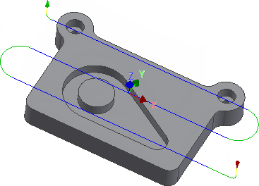
The toolpath is now calculated and a preview appears in the graphics window.

By default, the cutting parts of a toolpath are colored in blue, lead moves in green, and rapid moves in yellow. The start and end of the toolpath are indicated by a red and a green triangle respectively.
Continue to To Contour the Part (Tutorial 1)...