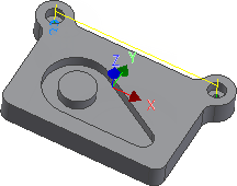
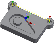
The next step is to drill the two small holes at the top left and right corners of the work piece.
- On the ribbon, click
CAM tab
 Drilling panel
 Drill
Drill
 .
.
 Tool tab
Change the default tool.
- On the
Tool tab, click the
 button.
- Click the
 button.
- Click the Cutter tab.
- Change Type to Drill by selecting it from the drop-down menu.
- Change Diameter to 5 mm.
- Click the OK button to create your new tool.
- Click the Select button to select the tool for your operation and close the Tool Library dialog.
This procedure creates a tool with default dimensions and cutting data. The default is a Ø10 mm drill. We will use most of the defaults, but change some of the cutting parameters a bit.
 Geometry tab
- Click the Geometry tab. Ensure that Selected faces is selected from the Hole mode: drop-down menu and that the Hole faces selection button is active.
- Zoom in, and select the cylindrical face of the smaller diameter hole at the top left corner of the part.

- Enable the
Select same diameter check box. Doing so automatically selects the identically sized small hole at the top right of the part.

 Heights tab
- Click the Heights tab and enable the Drill tip through bottom check box.
- Change Break-through depth to: 1 mm
 Cycle tab
- Click the Cycle tab.
- Select Chip breaking - partial retract from the Cycle type: drop-down menu.
Start the Calculation
- Click
 at the bottom of the
Operation dialog box, or right-click in the graphics window and select
OK from the marking menu, to automatically start calculating the toolpath.

Continue to To Tap Holes...