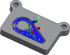
The next operation is to machine the pocket with the central circular boss on the top surface of the part.
- On the ribbon, click
CAM tab
 2D Milling panel
 2D Pocket
 .
.
 Tool tab
- On the
Tool tab, click the
 button and select the tool
#2 - Ø8 mm flat from the library.
- Click
 to close the
Tool Library dialog.
 Geometry tab
- Click the Geometry tab. The contours of the pocket to be cleared are selected here.
- Click anywhere on the face at the bottom of the pocket.

Note: Selecting faces for 2D geometry automatically uses all edges of the face for the contours. However, if two adjacent faces are selected, the edges they share are not included in the selection.
 Heights tab
- By default, the 2D Pocket operation machines from the top of the stock to the level of the selected contours. This is exactly what is needed in this operation, so there is no need to change any heights.
 Passes tab
- Click the Passes tab.
- Enable the Multiple Depths check box.
- Change Maximum roughing stepdown to: 2.0 mm
- Change Finishing stepdowns to: 1
- Disable the Stock to Leave check box.
This group of settings controls how the 2D pocket toolpath is calculated. To clear out the pocket, the toolpath is generated in a number of Z levels, starting from the top of the stock and going down in steps of 2 mm to the bottom of the pocket.
We do not want to leave any stock in this operation, and since this is a roughing operation, the default is to leave stock.
Start the Calculation
- Click
 at the bottom of the
Operation dialog box, or right-click in the graphics window and select
OK from the marking menu, to automatically start calculating the toolpath.
The toolpath is now calculated and shown in the graphics window.

Continue to To Machine the Counterbores...