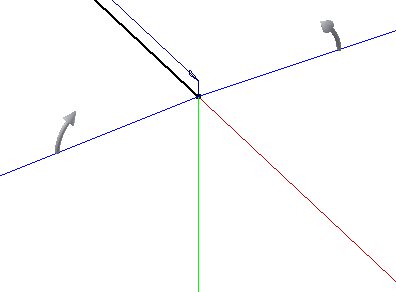
You activate the 3D Orthogonal Route tool when you create or reposition route points in a rigid type route, or place nodes for flexible hose routes that do not contain start or end fittings. It is also activated when you place or reposition fittings, unless the placement is fully defined by the connection data.
When the tool is active, click a point on a Direction Axes or Line Extender, drag a Rotation Arrow or the Rotation Handles, snap points from existing geometry onto a line, or click a 45-degree Angle Control. To position a route point at a specific angle or distance, enter a value using the keyboard or the context menu. For bent tube routes, you can also use the tool to enter a bend radius. For flexible hose routes you can offset nodes from selected faces.
 Show Me about the route tool with tube and pipe routes
How does the tool enable route point creation and editing?
The 3D Orthogonal Route tool enables interactive creation of all route types and editing of rigid route points. Valid route points vary depending on the connection data for the item selected, the action being performed, and the active style. With each selection, only those elements of the tool relating to valid points are displayed.
Valid route points vary depending on the connection data for the item selected, the action being performed, and the active style. With each selection, only those elements relating to valid points are displayed. For example, after selecting the start point for a rigid type route, allowed directions are normal to the selected edge. The first point is connected to the component, so perpendicular directions are not allowed and only the Line Extender is displayed. If a new point is an arbitrary point in space and 45-degree route directions are included in the selected style, all elements of the tool are displayed.
How does the tool differ for different route types?
For rigid pipe routes, the tool enables you to create or reposition route points and segments that are:
- Rotated freely or in 90-degree or 45-degree angles from the selected route point.
- Offset from the current route point.
- Snapped from existing geometry, such as faces, edges, work points, work planes.
- At a precise distance or angle from the current route point.
- Parallel to the selected edge or perpendicular to the selected planar face.
In addition to free rotation, point offset, and associative route point creation, use the tool to create or reposition bent tube route points that are:
- Rotated any angle between 0 and 360 degrees
- Defined with a bend radius. It works the same as you are creating a custom bend in rigid piping routes.
For rigid self-draining line routes, behavior is determined by the axis orientation to the defined gravity direction. At all times, either the red or green axis is parallel to the defined gravity direction.
When the green axis is parallel to the gravity direction:
- The blue axis is sloped to match the defined slope angle.
- The red axis is parallel to the defined slope angle.
- The blue axis arrows reverse the slope angle direction.

When the red axis is parallel to the gravity direction:
- The blue axis is sloped to match the defined slope angle.
- The green axis is parallel to the defined slope angle.
- The blue axis arrows reverse the slope angle direction.
For flexible hose routes with no start or end fittings, the tool elements provided are the same as those provided for bent tube type routes. The difference is that each selection you make creates a route point that controls hose segment shape, rather than creating a precise arc. In addition, you can select points offset from selected faces.
What do the tool colors mean?
When you activate the 3D Orthogonal Route tool, its origin is coincident with the last selected route point. The displayed direction axes represent the axes of the selected route point.
Because you can rotate the direction lines, the colors help you identify the axes. The colors correspond to the default colors of the principle assembly axes:
- Red is the X axis.
- Green is the Y axis.
- Blue is the Z axis.
How can I change the tool display?
Both tool appearance and size can be changed to suit your needs. When the tool is displayed, use the plus (+) and (-) keys on the numeric keypad to increase and reduce the size. For better visibility you can adjust the appearance for a selected Direction Axes or Line Extender and the tooltip displayed for points. Set the appearances using the appearance dropdown as described here.
